556881-7 TE Connectivity, 556881-7 Datasheet - Page 6
556881-7
Manufacturer Part Number
556881-7
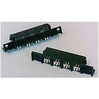
Description
RCPT ASY,VRT,AMPINRGY WTB,7POS
Manufacturer
TE Connectivity
Specifications of 556881-7
Voltage Rating
600 V
Number Of Positions / Contacts
7
Mounting Style
PCB
Termination Style
Solder
Contact Plating
Tin Lead
Contact Material
Copper Alloy
Product Type
Connector
Connector Type
Connector Assembly
Pcb Mounting Orientation
Vertical
Make First / Break Last
No
Pcb Mount Retention
Without
Termination Method To Pc Board
Through Hole - Solder
Pcb Mount Alignment
Without
Sealed
No
Ul File Number
E28476
Csa File Number
LR 7189
Mating Retention Type
Latching
Vde Tested
No
Contact - Rated Current (a)
35
Operating Voltage Reference
AC
Operating Voltage (vac)
600
Tail Length (mm [in])
4.9 [0.192]
Tail Orientation
In-line
Profile Height (y-axis) (mm [in])
12.70 [0.500]
Mating Retention
With
Number Of Positions
7
Centerline (mm [in])
11.18 [0.440]
Number Of Rows
1
Length (x-axis) (mm [in])
102.54 [4.040]
Width (z-axis) (mm [in])
19.30 [0.760]
Contact Base Material
Copper Alloy
Contact Type
Pin/Socket
Contact Design
Dual Beam
Contact Plating, Mating Area, Material
Tin
Contact Plating, Mating Area, Thickness (µm [?in])
3.81 [150]
Tail Plating Material
Tin
Tail Plating, Thickness (µm [?in])
2.54 [100]
Connector Style
Receptacle
Housing Material
Polyphenylene Sulfide
Housing Color
Black
Mating Alignment
With
Mating Alignment Type
Polarization
Ul Flammability Rating
UL 94V-0
Custom Configurable
No
Rohs/elv Compliance
RoHS compliant, ELV compliant
Lead Free Solder Processes
Not relevant for lead free process
Rohs/elv Compliance History
Always was RoHS compliant
Agency/standard
UL, CSA
Ul Rating
Recognized
Ul Voltage Rating (vac)
600
Csa Certified
Yes
Operating Temperature (°c [°f])
0 – 105 [32 – 221]
Applies To
Printed Circuit Board
Pcb Thickness, Recommended (mm [in])
1.57 – 3.18 [0.062 – 0.1251]
Application Use
Wire-to-Board
Contact Transmits (typical Application)
Power
Packaging Method
Loose Piece
Lead Free Status / Rohs Status
Details


Rev A
NOTE
NOTE
.062 inch thick printed circuit board, 2 ounce copper trace, double sided, .360 inch wide trace.
To determine acceptable current carrying capacity for the percentage connector loading and wire
gage indicated, use the Multiplication Factor (F) from the above chart and multiply it times the Base
rated Current for a single circuit at the maximum ambient operating temperature shown in Figure
4A.
Single Circuit 1
Percent Connector Loading
Single Contact
Rated Current vs Ambient Temperature Rating for
100
50
rms
or I
Current Carrying Capability
dc
, Maximum Wire Gage, Continuous Operating
Current Rating
Figure 4A
Figure 4B
.50
.46
.40
18
.62
.57
.50
16
Wire Size AWG
.75
.69
.60
14
.87
.80
.70
12
.92
.80
10
1
108-1349
6 of 7
Related parts for 556881-7
Image
Part Number
Description
Manufacturer
Datasheet
Request
R

Part Number:
Description:
RCPT ASY VRT AMPINRGY WTB 3POS
Manufacturer:
TE Connectivity
Datasheet:

Part Number:
Description:
Power to the Board RCPT ASY VRT WTB 6 POS
Manufacturer:
TE Connectivity
Datasheet:
Part Number:
Description:
Power to the Board RCPT ASY VRT WTB 5 POS
Manufacturer:
TE Connectivity
Datasheet:
Part Number:
Description:
Power to the Board RCPT ASY VRT WTB 8 POS
Manufacturer:
TE Connectivity
Datasheet:
Part Number:
Description:
Power to the Board RCPT ASY VRT WTB 4 POS
Manufacturer:
TE Connectivity
Datasheet:
Part Number:
Description:
2PIN WIRE TO BOARD CONN
Manufacturer:
TE Connectivity
Datasheet:

Part Number:
Description:
TT230SM Printer, label caddy, Tagprint Pro Software, a ribbon, hard case KIT
Manufacturer:
HellermannTyton

Part Number:
Description:
Printers THERMAL PRINTER HS-SLEEVE MARKER
Manufacturer:
TE Connectivity


Part Number:
Description:
Manufacturer:
TE Connectivity
Datasheet:


Part Number:
Description:
Manufacturer:
TE Connectivity
Datasheet:

Part Number:
Description:
Manufacturer:
TE Connectivity
Datasheet: