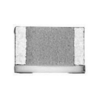
P1206Y1003BN Vishay, P1206Y1003BN Datasheet - Page 2

P1206Y1003BN
Manufacturer Part Number
P1206Y1003BN
Description
THIN FILM SFERNICE / P 1206 Y 1003 B N WP E2
Manufacturer
Vishay
Series
Pr
Datasheet
1.P1206E10R0BB.pdf
(10 pages)
Specifications of P1206Y1003BN
Resistance
100 KOhms
Tolerance
0.1 %
Package / Case
1206 (3216 metric)
Power Rating
0.33 Watt (1/3 Watt)
Voltage Rating
200 Volts
Operating Temperature Range
- 55 C to + 155 C
Termination Style
SMD/SMT
Dimensions
1.6 mm W x 3.06 mm L x 0.5 mm H
Product
Precision Resistors Thin Film SMD
Temperature Coefficient
+/- 10 PPM / C
Lead Free Status / RoHS Status
Lead free / RoHS Compliant
Lead Free Status / RoHS Status
Lead free / RoHS Compliant
SUGGESTED LAND PATTERN (to IPC-7351A)
Note
• Case size 2512 under development. Please consult Vishay Sfernice.
ELECTRICAL SPECIFICATIONS
Notes
•
(1)
(2)
Document Number: 53017
Revision: 14-Feb-11
CHIP SIZE
0302
0402
0505
0603
0705/0805
1005
1206
1505
2010
CASE SIZE
0302
0402
0505
0603
0705/0805
1005
1206
1505
2010
Case size 2512 under development. Please consult Vishay Sfernice.
Pn = Nominal power - Pd = Derated power intended to improve stability.
For ohmic range versus tolerance and TCR see detailed table page 62.
Pn
1000
125
125
200
250
330
350
POWER RATING
40
63
High Precision Wraparound - Wide Ohmic Value Range
(1)
mW
Pd
100
125
125
250
175
500
30
40
50
(1)
For technical questions, contact:
Z
1.30
1.55
1.82
2.37
2.76
3.39
3.91
4.66
5.93
max.
Thin Film Chip Resistors
LIMITING ELEMENT VOLTAGE
Z
max.
G
min.
150
200
300
25
50
50
75
75
75
DIMENSIONS (in millimeter)
V
sfer@vishay.com
G
0.14
0.15
0.10
0.35
0.74
1.37
1.85
2.44
3.71
min.
X
max.
RESISTANCE RANGE
10 to 500 k
10 to 1.5 M
10 to 2.5 M
10 to 10 M
10 to 35 M
10 to 10 M
10 to 50 M
Vishay Sfernice
10 to 4 M
10 to 5 M
X
0.73
0.73
1.40
0.98
1.40
1.40
1.73
1.45
2.67
max.
www.vishay.com
(2)
P
61


