AD7884AQ Analog Devices Inc, AD7884AQ Datasheet - Page 2
AD7884AQ
Manufacturer Part Number
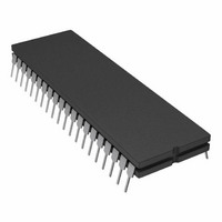
AD7884AQ
Description
IC,A/D CONVERTER,SINGLE,16-BIT,CMOS,DIP,40PIN
Manufacturer
Analog Devices Inc
Datasheet
1.AD7885AAPZ.pdf
(16 pages)
Specifications of AD7884AQ
Rohs Status
RoHS non-compliant
Number Of Bits
16
Sampling Rate (per Second)
166k
Data Interface
Parallel
Number Of Converters
2
Power Dissipation (max)
325mW
Voltage Supply Source
Dual ±
Operating Temperature
-40°C ~ 85°C
Mounting Type
Through Hole
Package / Case
40-CDIP (0.600", 15.24mm)
Lead Free Status / RoHS Status
Available stocks
Company
Part Number
Manufacturer
Quantity
Price


AD7884/AD7885/AD7885A–SPECIFICATIONS
V
Parameter
DC ACCURACY
DYNAMIC PERFORMANCE
CONVERSION TIME
ANALOG INPUT
REFERENCE INPUT
LOGIC INPUTS
LOGIC OUTPUTS
POWER REQUIREMENTS
NOTES
1
2
3
4
Specifications subject to change without notice.
Temperature ranges are as follows: J, A, B Versions: –40°C to +85°C.
V
The AD7885AAP has the same specifications as the AD7884AP. The AD7885ABP has the same specifications as the AD7884BP.
Sample tested to ensure compliance.
REF+
Resolution
Minimum Resolution for Which
Integral Nonlinearity
Positive Gain Error
Positive Gain Error
Bipolar Zero Error
Bipolar Zero TC
Negative Gain Error
Negative Gain Error
Noise
Signal-to-(Noise + Distortion) Ratio
Total Harmonic Distortion
Peak Harmonic or Spurious Noise
Intermodulation Distortion (IMD)
Conversion Time
Acquisition Time
Throughput Rate
Voltage Range
Input Current
Reference Input Current
Input High Voltage, V
Input Low Voltage, V
Input Current, I
Input Capacitance, C
Output High Voltage, V
Output Low Voltage, V
DB15–DB0
V
V
I
I
Power Supply Rejection Ratio
Power Dissipation
IN
DD
SS
DD
SS
No Missing Codes Are Guaranteed 16
Gain TC
Offset TC
Second Order Terms
Third Order Terms
Floating-State Leakage Current
Floating-State Output Capacitance
∆Gain/∆V
∆Gain/∆V
= ± 5 V.
S = 3 V, AGND = DGND = GND = 0 V, f
4
DD
SS
4
IN
4
IN
INL
INH
4
OL
OH
4
J
Version
16
± 0.1
± 2
± 0.05
± 8
± 0.1
± 2
120
82
82
–84
–84
–88
–84
–84
5.3
2.5
166
± 5
± 3
± 4
± 5
2.4
0.8
± 10
10
4.0
0.4
10
15
5
–5
35
30
33
86
86
325
SAMPLE
1, 2, 3
= 166 kHz. All specifications T
A
Version
16
16
± 0.03
± 2
± 0.05
± 8
± 0.03
± 2
120
84
82
–88
–84
–88
–84
–84
5.3
2.5
166
± 5
± 3
± 4
± 5
2.4
0.8
± 10
10
4.0
0.4
10
15
5
–5
35
30
33
86
86
325
1, 2, 3
B
Version
16
16
± 0.0075
± 0.03
± 0.05
± 2
± 0.05
± 0.15
± 8
± 0.03
± 0.05
± 2
120
84
82
–88
–84
–88
–84
–84
5.3
2.5
166
± 5
± 3
± 4
± 5
2.4
0.8
± 10
10
4.0
0.4
10
15
5
–5
35
30
33
86
86
325
–2–
1, 2, 3
Unit
Bits
Bits
% FSR max
% FSR typ
% FSR max
ppm FSR/°C typ
% FSR typ
% FSR max
ppm FSR/°C typ
% FSR typ
% FSR max
ppm FSR/°C typ
µV rms typ
dB min
dB typ
dB max
dB typ
dB max
dB typ
dB typ
µs max
µs max
kSPS max
V
V
mA max
mA max
V min
V max
µA max
pF max
V min
V max
µA max
pF max
V nom
V nom
mA max
mA max
mA max
dB typ
dB typ
mW max
MIN
to T
MAX
, unless otherwise noted.)
Test Conditions/Comments
Typically 0.003% FSR
AD7885AQ/BQ: 0.1% typ
AD7885BQ: 0.2% max
AD7885AQ/BQ: 0.1% typ
AD7885BQ: 0.2% max
78 µV rms Typical in ± 3 V Input Range
Input Signal: ±5 V, 1 kHz Sine Wave, Typically 86 dB
Input Signal: ± 5 V, 12 kHz Sine Wave
Input Signal: ± 5 V, 1 kHz Sine Wave
Input Signal: ± 5 V, 12 kHz Sine Wave
Input Signal: ± 5 V, 1 kHz Sine Wave
f
f
There is an overlap between conversion and acquisition.
V
V
V
Input Level = 0 V to V
I
I
± 5% for Specified Performance
± 5% for Specified Performance
Typically 25 mA
Typically 25 mA; AD7885/AD7885A
Typically 25 mA; AD7884
Typically 250 mW
(V
A
A
SOURCE
SINK
REF+
DD
DD
= 11.5 kHz, f
= 11.5 kHz, f
DD
= 5 V ± 5%
= 5 V ± 5%
= 1.6 mA
S = 3 V
= +5 V
= 200 µA
B
B
= 12 kHz, f
= 12 kHz, f
5%, V
DD
SS
= –5 V
SAMPLE
SAMPLE
= 166 kHz
= 166 kHz
5%,
REV. E
Related parts for AD7884AQ
Image
Part Number
Description
Manufacturer
Datasheet
Request
R

Part Number:
Description:
±1.7g Dual-Axis IMEMS Accelerometer Evaluation Board
Manufacturer:
Analog Devices Inc
Datasheet:

Part Number:
Description:
Inertial Sensor Evaluation System
Manufacturer:
Analog Devices Inc
Datasheet:
Part Number:
Description:
Manufacturer:
Analog Devices Inc
Datasheet:
Part Number:
Description:
Manufacturer:
Analog Devices Inc
Datasheet:
Part Number:
Description:
Manufacturer:
Analog Devices Inc
Datasheet:
Part Number:
Description:
Manufacturer:
Analog Devices Inc
Datasheet:
Part Number:
Description:
Manufacturer:
Analog Devices Inc
Datasheet:
Part Number:
Description:
Manufacturer:
Analog Devices Inc
Datasheet:
Part Number:
Description:
Manufacturer:
Analog Devices Inc
Datasheet:
Part Number:
Description:
Manufacturer:
Analog Devices Inc
Datasheet:
Part Number:
Description:
Manufacturer:
Analog Devices Inc
Datasheet:
Part Number:
Description:
Manufacturer:
Analog Devices Inc
Datasheet:
Part Number:
Description:
Manufacturer:
Analog Devices Inc
Datasheet: