AD7884AQ Analog Devices Inc, AD7884AQ Datasheet - Page 7
AD7884AQ
Manufacturer Part Number
AD7884AQ
Description
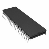
IC,A/D CONVERTER,SINGLE,16-BIT,CMOS,DIP,40PIN
Manufacturer
Analog Devices Inc
Datasheet
1.AD7885AAPZ.pdf
(16 pages)
Specifications of AD7884AQ
Rohs Status
RoHS non-compliant
Number Of Bits
16
Sampling Rate (per Second)
166k
Data Interface
Parallel
Number Of Converters
2
Power Dissipation (max)
325mW
Voltage Supply Source
Dual ±
Operating Temperature
-40°C ~ 85°C
Mounting Type
Through Hole
Package / Case
40-CDIP (0.600", 15.24mm)
Lead Free Status / RoHS Status
Available stocks
Company
Part Number
Manufacturer
Quantity
Price


AD7884
V
V
± 3V
± 3V
± 5V
± 5V
AGNDS
AGNDF
AV
AV
GND
V
V
CONVST
CS
RD
BUSY
DB0–DB15
DGND
V
V
REV. E
INV
REF–
SS
DD
REF+
REF+
DD
SS
IN
IN
IN
IN
F
S
S
F
S
F
AD7885
V
V
± 3V
± 5V
± 5V
AGNDS
AGNDF
AV
AV
GND
V
V
CONVST
CS
RD
HBEN
BUSY
DB0–DB7
DGND
V
V
INV
REF–
SS
DD
REF+
REF+
DD
SS
IN
IN
IN
F
S
S
F
AD7885A
V
V
± 3V
± 3V
± 5V
± 5V
AGNDS
AGNDF
AV
AV
GND
V
V
CONVST
CS
RD
HBEN
BUSY
DB0–DB7
DGND
V
V
INV
REF–
SS
DD
REF+
REF+
DD
SS
IN
IN
IN
IN
F
S
S
F
S
F
Description
This pin is connected to the inverting terminal of an op amp, as in Figure 6, and allows
the inversion of the supplied 3 V reference.
This is the negative reference input and can be obtained by using an external amplifier to
invert the positive reference input. In this case, the amplifier output is connected to V
See Figure 6.
This is the analog input sense pin for the ± 3 V analog input range on the AD7884 and
AD7885A.
This is the analog input force pin for the ± 3 V analog input range on the AD7884 and
AD7885A. When using this input range, the ± 5V
AGND.
This is the analog input pin for the ± 3 V analog input range on the AD7885. When using
this input range, the ± 5V
This is the analog input sense pin for the ±5 V analog input range on the AD7884, AD7885,
and AD7885A.
This is the analog input force pin for the ±5 V analog input range on the AD7884, AD7885,
and AD7885A. When using this input range, the ± 3V
to AGND.
This is the ground return sense pin for the 9-bit ADC and the on-chip residue amplifier.
This is the ground return force pin for the 9-bit ADC and the on-chip residue amplifier.
Positive analog power rail for the sample-and-hold amplifier and the residue amplifier.
Negative analog power rail for the sample-and-hold amplifier and the residue amplifier.
This is the ground return for the sample-and-hold section.
Negative Supply for the 9-Bit ADC
Positive Supply for the 9-Bit ADC and All Device Logic
This asynchronous control input starts conversion.
Chip Select Control Input
Read Control Input. This is used in conjunction with CS to read the conversion result
from the device output latch.
High Byte Enable. Active high control input for the AD7885. It selects either the high or
the low byte of the conversion for reading.
Busy Output. The BUSY output goes low when the conversion begins and stays low until
it is completed, at which time it goes high.
16-Bit Parallel Data-Word Output on the AD7884
8-Bit Parallel Data Byte Output on the AD7885
Ground Return for All Device Logic
Reference Force Input
Reference Sense Input. The device operates from a 3 V reference.
PIN FUNCTION DESCRIPTIONS
–7–
IN
F and ± 5V
IN
S pins should be tied to AGND.
IN
F and ± 5V
IN
F and ± 3V
AD7884/AD7885
IN
S pins should be tied to
IN
S pins should be tied
REF–
.
Related parts for AD7884AQ
Image
Part Number
Description
Manufacturer
Datasheet
Request
R

Part Number:
Description:
±1.7g Dual-Axis IMEMS Accelerometer Evaluation Board
Manufacturer:
Analog Devices Inc
Datasheet:

Part Number:
Description:
Inertial Sensor Evaluation System
Manufacturer:
Analog Devices Inc
Datasheet:
Part Number:
Description:
Manufacturer:
Analog Devices Inc
Datasheet:
Part Number:
Description:
Manufacturer:
Analog Devices Inc
Datasheet:
Part Number:
Description:
Manufacturer:
Analog Devices Inc
Datasheet:
Part Number:
Description:
Manufacturer:
Analog Devices Inc
Datasheet:
Part Number:
Description:
Manufacturer:
Analog Devices Inc
Datasheet:
Part Number:
Description:
Manufacturer:
Analog Devices Inc
Datasheet:
Part Number:
Description:
Manufacturer:
Analog Devices Inc
Datasheet:
Part Number:
Description:
Manufacturer:
Analog Devices Inc
Datasheet:
Part Number:
Description:
Manufacturer:
Analog Devices Inc
Datasheet:
Part Number:
Description:
Manufacturer:
Analog Devices Inc
Datasheet:
Part Number:
Description:
Manufacturer:
Analog Devices Inc
Datasheet: