AD569BD Analog Devices Inc, AD569BD Datasheet - Page 7
AD569BD
Manufacturer Part Number
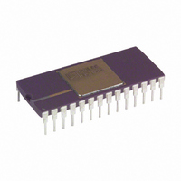
AD569BD
Description
IC,D/A CONVERTER,SINGLE,16-BIT,BICMOS,DIP,28PIN
Manufacturer
Analog Devices Inc
Datasheet
1.AD569JNZ.pdf
(12 pages)
Specifications of AD569BD
Rohs Status
RoHS non-compliant
Settling Time
4µs
Number Of Bits
16
Data Interface
Parallel
Number Of Converters
1
Voltage Supply Source
Dual ±
Operating Temperature
-25°C ~ 85°C
Mounting Type
Through Hole
Package / Case
28-CDIP (0.600", 15.24mm)
Power Dissipation (max)
-
Lead Free Status / RoHS Status
Available stocks
Company
Part Number
Manufacturer
Quantity
Price


benefit is that, should a Zener diode fail (a short circuit would
be the most likely failure), the supply voltage decreases. This
differs from the situation where the diode is used as a series
regulator. In that case, a failure would place the unregulated
supply voltage on the AD569 terminal.
REV. A
d. AD588 Produces References and Supply Voltages
a. Zener Regulates Negative Supply
b. Diodes Regulate Both Supplies
c. Use of 15 V and 5 V Supplies
Figure 7. Power Supply Options
–7–
ANALOG CIRCUIT CONNECTIONS
The AD569 is intended for use in applications where high reso-
lution and stability are critical. Designed as a multiplying D/A
converter, the AD569 may be used with a fixed dc reference or
an ac reference. V
voltages at +V
set for reference voltages as discussed in the power supply range
section. Since the AD569 is a multiplying D/A converter, its
output voltage, V
tal input word and the voltage at the reference terminal. The
transfer function is V
nary value of the digital word applied to the converter using
offset-binary coding. Therefore, the output will range from
–V
an input code of all ones (FFFF
For applications where absolute accuracy is not critical, the
simple reference connection in Figure 8 can be used. Using only
the reference force inputs, this configuration maintains linearity
and 16-bit monotonicity, but introduces small, fixed offset and
gain errors. These errors are due to the voltage drops across re-
sistors R
voltage, the gain and offset errors will range from 80 mV to
100 mV. Resistors R
string to avoid degraded linearity due to uneven current densi-
ties at the string’s endpoints. Similarly, linearity would degrade
if the reference voltage were connected across the reference
sense terminals. Note that the resistance between the force and
sense terminals cannot be measured with an ohmmeter; the lay-
out of the thin-film resistor string adds approximately 4 k of
resistance (R
For those applications in which precision references and high
accuracy are critical, buffer amplifiers are used at +V
–V
R1 to R256. This insures that any errors induced by currents
flowing through the resistances of the package pins, bond wires,
aluminum interconnections, as well as R
mized. Suitable amplifiers are the AD517, AD OP07, AD OP27,
or the dual amplifier, the AD712. Errors will arise, however, as
the buffer amplifiers’ bias currents flow through R
the bias currents produce such errors, resistance can be inserted
at the noninverting terminal (R
compensate for the errors.
REF
REF
for a digital input code of all zeros (0000
as shown in Figure 10 to force the voltage across resistors
A
and R
Figure 8. Simple Reference Connection
S
) at the sense tap.
FORCE
B
OUT
REF
shown in Figure 9. With a 10 V reference
and –V
A
, is proportional to the product of the digi-
OUT
may be any voltage or combination of
and R
= D·V
FORCE
B
were included in the first resistor
BC
REF
H
).
) of the buffer amplifiers to
that remain within the bounds
where D is the fractional bi-
A
and R
H
B
) to +V
AD569
are mini-
S
(4 k ). If
REF
REF
and
for
Related parts for AD569BD
Image
Part Number
Description
Manufacturer
Datasheet
Request
R

Part Number:
Description:
DPG2 EVAL ADAPTER FOR XILINX BOARDS
Manufacturer:
Analog Devices Inc
Part Number:
Description:
Xilinx FMC Interface
Manufacturer:
Analog Devices Inc
Datasheet:
Part Number:
Description:
Xilinx FMC Interface
Manufacturer:
Analog Devices Inc
Datasheet:
Part Number:
Description:
Xilinx FMC Interface
Manufacturer:
Analog Devices Inc
Datasheet:
Part Number:
Description:
Xilinx FMC Interface
Manufacturer:
Analog Devices Inc
Datasheet:
Part Number:
Description:
Xilinx FMC Interface
Manufacturer:
Analog Devices Inc
Datasheet:
Part Number:
Description:
Xilinx FMC Interface
Manufacturer:
Analog Devices Inc
Datasheet:
Part Number:
Description:
Xilinx FMC Interface
Manufacturer:
Analog Devices Inc
Datasheet:
Part Number:
Description:
AD CONVERTOR, IC, BIT COUNT FOR PROCESSOR
Manufacturer:
Analog Devices Inc

Part Number:
Description:
±1.7g Dual-Axis IMEMS Accelerometer Evaluation Board
Manufacturer:
Analog Devices Inc
Datasheet:
Part Number:
Description:
Inertial Sensor Evaluation System
Manufacturer:
Analog Devices Inc
Datasheet:
Part Number:
Description:
Manufacturer:
Analog Devices Inc
Datasheet: