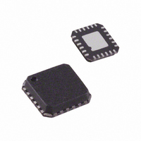
AD7147PACPZ-RL Analog Devices Inc, AD7147PACPZ-RL Datasheet - Page 23

AD7147PACPZ-RL
Manufacturer Part Number
AD7147PACPZ-RL
Description
CAPACITANCE TO DIGITAL CONVERTER
Manufacturer
Analog Devices Inc
Series
CapTouch™r
Type
Capacitive Sensor Controllerr
Datasheet
1.AD7147ACPZ-1500RL7.pdf
(72 pages)
Specifications of AD7147PACPZ-RL
Resolution (bits)
16 b
Data Interface
I²C
Voltage Supply Source
Single Supply
Voltage - Supply
2.6 V ~ 3.6 V
Operating Temperature
-40°C ~ 85°C
Mounting Type
Surface Mount
Package / Case
24-LFCSP
Lead Free Status / RoHS Status
Lead free / RoHS Compliant
Sampling Rate (per Second)
-
Lead Free Status / RoHS Status
Lead free / RoHS Compliant
Available stocks
Company
Part Number
Manufacturer
Quantity
Price
Part Number:
AD7147PACPZ-RL
Manufacturer:
ADI/亚德诺
Quantity:
20 000
ENVIRONMENTAL CALIBRATION
The AD7147 provides on-chip capacitance sensor calibration to
automatically adjust for environmental conditions that have an
effect on the ambient levels of the capacitance sensor. The output
levels of the capacitance sensor are sensitive to temperature,
humidity, and, in some cases, dirt.
The AD7147 achieves optimal and reliable sensor performance
by continuously monitoring the CDC ambient levels and compen-
sating for any environmental changes by adjusting the values of
the STAGEx_HIGH_THRESHOLD register and the STAGEx_
LOW_THRESHOLD registers as described in the Threshold
Equations section. The CDC ambient level is defined as the
output level of the capacitance sensor during periods when the
user is not approaching or in contact with the sensor.
After the AD7147 is configured, the compensation logic runs
automatically with each conversion when the AD7147 is not
being touched. This allows the AD7147 to compensate for
rapidly changing environmental conditions.
The ambient compensation control registers provide the host
with access to general setup and controls for the compensation
algorithm. On-chip RAM stores the compensation data for each
conversion stage, as well as setup information specific for each stage.
Figure 35 shows an example of the ideal behavior of a capaci-
tance sensor, where the CDC ambient level remains constant
regardless of the environmental conditions. The CDC output
shown is for a pair of differential button sensors, where one
sensor caused an increase and the other caused a decrease in
measured capacitance when activated. The positive and negative
sensor threshold levels are calculated as a percentage of the
STAGEx_OFFSET_HIGH and STAGEx_OFFSET_LOW values
and are based on the threshold sensitivity settings and the
ambient value. These values are sufficient to detect a sensor
contact and result in the AD7147 asserting the INT output
when the threshold levels are exceeded.
Rev. B | Page 23 of 72
CAPACITANCE SENSOR BEHAVIOR WITHOUT
CALIBRATION
Figure 36 shows the typical behavior of a capacitance sensor
when calibration is not applied. This figure shows ambient
levels drifting over time as environmental conditions change. As
a result of the initial threshold levels remaining constant while
the ambient levels drift upward, Sensor 2 fails to detect a user
contact in this example.
The Capacitance Sensor Behavior with Calibration section
describes how the AD7147 adaptive calibration algorithm
prevents such errors from occurring.
CHANGING ENVIRONMENTAL CONDITIONS
CHANGING ENVIRONMENTAL CONDITIONS
Figure 35. Ideal Sensor Behavior with a Constant Ambient Level
Figure 36. Typical Sensor Behavior Without Calibration
NOT ASSERTED
SENSOR 2 INT
SENSOR 2 INT
ASSERTED
SENSOR 1 INT
SENSOR 1 INT
ASSERTED
ASSERTED
t
t
STAGEx_HIGH_THRESHOLD
CDC AMBIENT VALUE
STAGEx_LOW_THRESHOLD
STAGEx_HIGH_THRESHOLD
CDC AMBIENT
VALUE DRIFTING
STAGEx_LOW_THRESHOLD
AD7147


