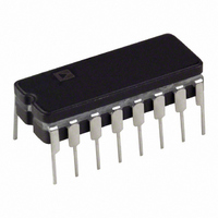
AD96687BQ Analog Devices Inc, AD96687BQ Datasheet - Page 3

AD96687BQ
Manufacturer Part Number
AD96687BQ
Description
Voltage Comparator IC
Manufacturer
Analog Devices Inc
Type
with Latchr
Datasheet
1.AD96687BRZ.pdf
(8 pages)
Specifications of AD96687BQ
Package / Case
16-DIP
Number Of Elements
2
Output Type
Complementary, ECL, Open-Emitter
Mounting Type
Through Hole
Lead Free Status / RoHS Status
Contains lead / RoHS non-compliant
Available stocks
Company
Part Number
Manufacturer
Quantity
Price
Part Number:
AD96687BQ
Manufacturer:
ADI/亚德诺
Quantity:
20 000
ABSOLUTE MAXIMUM RATINGS
Positive Supply Voltage (+V
Negative Supply Voltage (–V
Input Voltage Range
Differential Input Voltage . . . . . . . . . . . . . . . . . . . . . . . . 5.5 V
Latch Enable Voltage . . . . . . . . . . . . . . . . . . . . . . . . –V
Output Current . . . . . . . . . . . . . . . . . . . . . . . . . . . . . . . 30 mA
Operating Temperature Range
Storage Temperature Range . . . . . . . . . . . . –55°C to +150°C
Junction Temperature . . . . . . . . . . . . . . . . . . . . . . . . . . 175°C
Lead Soldering Temperature (10 sec) . . . . . . . . . . . . . . 300°C
NOTES
1
2
3
Pin Name
+V
NONINVERTING INPUT
INVERTING INPUT
LATCH ENABLE
LATCH ENABLE
–V
Q
Q
GROUND 1
GROUND 2
Absolute maximum ratings are limiting values, may be applied individually, and
Under no circumstances should the input voltages exceed the supply voltages.
Typical thermal impedances . . .
beyond which serviceability of the circuit may be impaired. Functional operation
under any of these conditions is not necessarily implied. Exposure to absolute
maximum rating conditions for extended periods may affect device reliability.
AD96685BR/AD96687BQ/BR/BP . . . . . . . –25°C to +85°C
S
AD96685 SOIC
AD96687 Ceramic
AD96687 SOIC
AD96687 PLCC
S
2
. . . . . . . . . . . . . . . . . . . . . . . . . . . . ± 5 V
q
q
q
q
JA
JA
JA
JA
= 170°C/W; q
= 115°C/W; q
= 92°C/W; q
= 81°C/W; q
S
S
) . . . . . . . . . . . . . . . . . . . . . 6.5 V
) . . . . . . . . . . . . . . . . . . . –6.5 V
3
Description
Positive supply terminal, nominally 5.0 V.
Noninverting analog input of the differential input stage. The NONINVERTING INPUT must be
driven in conjunction with the INVERTING INPUT.
Inverting analog input of the differential input stage. The INVERTING INPUT must be driven in
conjunction with the NONINVERTING INPUT.
In the “compare” mode (logic HIGH), the output will track changes at the input of the compara-
tor. In the “latch” mode (logic LOW), the output will reflect the input state just prior to the
comparator being placed in the “latch” mode. LATCH ENABLE must be driven in conjunction
with LATCH ENABLE for the AD96687.
In the “compare” mode (logic LOW), the output will track changes at the input of the comparator.
In the “latch” mode (logic HIGH), the output will reflect the input state just prior to the comparator
being placed in the “latch” mode. LATCH ENABLE must be driven in conjunction with
LATCH ENABLE for the AD96687.
Negative supply terminal, nominally –5.2 V.
One of two complementary outputs. Q will be at logic HIGH if the analog voltage at the
NONINVERTING INPUT is greater than the analog voltage at the INVERTING INPUT (pro-
vided the comparator is in the “compare” mode). See LATCH ENABLE and LATCH ENABLE
(AD96687 only) for additional information.
One of two complementary outputs. Q will be at logic LOW if the analog voltage at the
NONINVERTING INPUT is greater than the analog voltage at the INVERTING INPUT
(provided the comparator is in the “compare” mode). See LATCH ENABLE and LATCH ENABLE
(AD96687 only) for additional information.
One of two grounds, but primarily associated with the digital ground. Both grounds should be
connected together near the comparator.
One of two grounds, but primarily associated with the analog ground. Both grounds should be
connected together near the comparator.
JC
JC
1
JC
JC
= 47°C/W
= 45°C/W
= 60°C/W
= 57°C/W
FUNCTIONAL DESCRIPTION
S
to 0 V
EXPLANATION OF TEST LEVELS
Test Level
I
II – 100% production tested at 25°C, and sample tested at
III – Sample tested only.
IV – Parameter is guaranteed by design and characterization
V – Parameter is a typical value only.
VI – All devices are 100% production tested at 25°C; 100%
– 100% production tested.
specified temperatures.
testing.
production tested at temperature extremes for extended
temperature devices; sample tested at temperature ex-
tremes for commercial/industrial devices.
AD96685/AD96687


