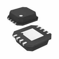
ADP3334ACPZ-REEL7 Analog Devices Inc, ADP3334ACPZ-REEL7 Datasheet - Page 9

ADP3334ACPZ-REEL7
Manufacturer Part Number
ADP3334ACPZ-REEL7
Description
IC,VOLT REGULATOR,ADJUSTABLE,+1.5 TO +10V,BIPOLAR,LLCC,8PIN,PLASTIC
Manufacturer
Analog Devices Inc
Series
anyCAP®r
Datasheet
1.ADP3334ACPZ-REEL7.pdf
(12 pages)
Specifications of ADP3334ACPZ-REEL7
Package / Case
8-LFCSP
Mounting Type
Surface Mount
Current - Output
500mA
Voltage - Output
1.5 ~ 10 V
Voltage - Input
2.6 ~ 11 V
Operating Temperature
-40°C ~ 85°C
Regulator Topology
Positive Adjustable
Voltage - Dropout (typical)
0.2V @ 500mA
Number Of Regulators
1
Lead Free Status / RoHS Status
Lead free / RoHS Compliant
Current - Limit (min)
-
Lead Free Status / RoHS Status
Lead free / RoHS Compliant
Available stocks
Company
Part Number
Manufacturer
Quantity
Price
Company:
Part Number:
ADP3334ACPZ-REEL7
Manufacturer:
SEIKO
Quantity:
40 000
Part Number:
ADP3334ACPZ-REEL7
Manufacturer:
ADI/亚德诺
Quantity:
20 000
3. The solder mask opening should be about 120 microns
4. The paste mask opening is typically designed to match the
5. The recommended paste mask stencil thickness is 0.125 mm.
6. The package manufacturer recommends that the reflow
REV. B
(4.7 mils) larger than the pad size resulting in a minimum
60 micron (2.4 mils) clearance between the pad and the
solder mask.
pad size used on the peripheral pads of the LFCSP package.
This should provide a reliable solder joint as long as the
stencil thickness is about 0.125 mm.
The paste mask for the thermal pad needs to be designed for
the maximum coverage to effectively remove the heat from the
package. However, due to the presence of thermal vias and the
size of the thermal pad, eliminating voids may not be possible.
A laser cut stainless steel stencil with trapezoidal walls should
be used.
A “No Clean” Type 3 solder paste should be used for mount-
ing the LFCSP package. Also, a nitrogen purge during the
reflow process is recommended.
temperature should not exceed 220°C and the time above
liquidus is less than 75 seconds. The preheat ramp should be
3°C/second or lower. The actual temperature profile depends
on the board density and must determined by the assembly
house as to what works best.
–9–
Use the following general guidelines when designing printed
circuit boards.
1. Keep the output capacitor as close as possible to the out-
2. Keep the input capacitor as close as possible to the input
3. PC board traces with larger cross sectional areas will remove
4. Use additional copper layers or planes to reduce the
Shutdown Mode
Applying a TTL high signal to the shutdown (SD) pin or the
input pin will turn the output off. Pulling SD down to 0.4 V or
below or tying it to ground will turn the output on. In shutdown
mode, quiescent current is reduced to much less than 1 µA.
put and ground pins.
and ground pins.
more heat from the ADP3334. For optimum heat transfer,
specify thick copper and use wide traces.
thermal resistance. When connecting to other layers, use
multiple vias if possible.
ADP3334


