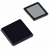
ADUC843BCP32Z-5 Analog Devices Inc, ADUC843BCP32Z-5 Datasheet - Page 63

ADUC843BCP32Z-5
Manufacturer Part Number
ADUC843BCP32Z-5
Description
Microconverter, ADUC842 Without DACs
Manufacturer
Analog Devices Inc
Series
MicroConverter® ADuC8xxr
Datasheet
1.EVAL-ADUC842QS.pdf
(88 pages)
Specifications of ADUC843BCP32Z-5
Core Processor
8052
Core Size
8-Bit
Speed
16.78MHz
Connectivity
I²C, SPI, UART/USART
Peripherals
DMA, PSM, PWM, Temp Sensor, WDT
Number Of I /o
32
Program Memory Size
32KB (32K x 8)
Program Memory Type
FLASH
Ram Size
2.25K x 8
Voltage - Supply (vcc/vdd)
4.75 V ~ 5.25 V
Data Converters
A/D 8x12b
Oscillator Type
Internal
Operating Temperature
-40°C ~ 85°C
Package / Case
56-LFCSP
Lead Free Status / RoHS Status
Lead free / RoHS Compliant
Eeprom Size
-
Lead Free Status / RoHS Status
Lead free / RoHS Compliant
T2CON
SFR Address
Power-On Default
Bit Addressable
Table 30. T2CON SFR Bit Designations
Bit No.
7
6
5
4
3
2
1
0
Timer/Counter 2 Data Registers
Timer/Counter 2 also has two pairs of 8-bit data registers
associated with it. These are used as both timer data registers
and as timer capture/reload registers.
TH2 and TL2
Timer 2, data high byte and low byte.
SFR Address = CDH, CCH, respectively.
RCAP2H and RCAP2L
Timer 2, capture/reload byte and low byte.
SFR Address = CBH, CAH, respectively.
Name
TF2
EXF2
RCLK
TCLK
EXEN2
TR2
CNT2
CAP2
Description
Timer 2 Overflow Flag.
Set by hardware on a Timer 2 overflow. TF2 cannot be set when either RCLK = 1 or TCLK = 1.
Cleared by user software.
Timer 2 External Flag.
Set by hardware when either a capture or reload is caused by a negative transition on T2EX and EXEN2 = 1.
Cleared by user software.
Receive Clock Enable Bit.
Set by the user to enable the serial port to use Timer 2 overflow pulses for its receive clock in serial port Modes 1 and 3.
Cleared by the user to enable Timer 1 overflow to be used for the receive clock.
Transmit Clock Enable Bit.
Set by the user to enable the serial port to use Timer 2 overflow pulses for its transmit clock in serial port Modes 1 and 3.
Cleared by the user to enable Timer 1 overflow to be used for the transmit clock.
Timer 2 External Enable Flag.
Set by the user to enable a capture or reload to occur as a result of a negative transition on T2EX if Timer 2 is not being
used to clock the serial port.
Cleared by the user for Timer 2 to ignore events at T2EX.
Timer 2 Start/Stop Control Bit.
Set by the user to start Timer 2.
Cleared by the user to stop Timer 2.
Timer 2 Timer or Counter Function Select Bit.
Set by the user to select counter function (input from external T2 pin).
Cleared by the user to select timer function (input from on-chip core clock).
Timer 2 Capture/Reload Select Bit.
Set by the user to enable captures on negative transitions at T2EX if EXEN2 = 1.
Cleared by the user to enable autoreloads with Timer 2 overflows or negative transitions at T2EX when EXEN2 = 1.
When either RCLK = 1 or TCLK = 1, this bit is ignored and the timer is forced to autoreload on Timer 2 overflow.
Timer/Counter 2 Control Register
C8H
00H
Yes
Rev. 0 | Page 63 of 88
ADuC841/ADuC842/ADuC843


