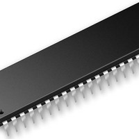
DSPIC33FJ16GS504-E/TL Microchip Technology, DSPIC33FJ16GS504-E/TL Datasheet - Page 13

DSPIC33FJ16GS504-E/TL
Manufacturer Part Number
DSPIC33FJ16GS504-E/TL
Description
16 Bit MCU/DSP 40MIPS 16 KB FLASH 2KB RAM SMPS 44 TLA 6x6x0.9 Mm TUBE
Manufacturer
Microchip Technology
Series
dsPIC™ 33Fr
Datasheet
1.DSPIC33FJ16GS404-ETL.pdf
(16 pages)
Specifications of DSPIC33FJ16GS504-E/TL
Core Processor
dsPIC
Core Size
16-Bit
Speed
40 MIPs
Connectivity
I²C, IrDA, LIN, SPI, UART/USART
Peripherals
Brown-out Detect/Reset, POR, PWM, WDT
Number Of I /o
35
Program Memory Size
16KB (16K x 8)
Program Memory Type
FLASH
Ram Size
2K x 8
Voltage - Supply (vcc/vdd)
3 V ~ 3.6 V
Data Converters
A/D 12x10b, D/A 1x10b
Oscillator Type
Internal
Operating Temperature
-40°C ~ 125°C
Package / Case
*
Processor Series
dsPIC33FJ
Core
dsPIC
Data Bus Width
16 bit
Data Ram Size
2 KB
Interface Type
I2C, SPI, UART
Maximum Clock Frequency
40 MHz
Number Of Programmable I/os
35
Operating Supply Voltage
3 V to 3.6 V
Maximum Operating Temperature
+ 125 C
Mounting Style
Through Hole
Development Tools By Supplier
DM240001, DM240002
Lead Free Status / RoHS Status
Lead free / RoHS Compliant
Eeprom Size
-
Lead Free Status / Rohs Status
Details
Advanced Development Tools and Reference Designs
Digital Pure Sine Wave Uninterruptible Power Supply
(UPS) Reference Design
This reference design demonstrates how digital-power
Thi
techniques when applied to UPS applications enable
easy modifications through software, the use of
smaller magnetics, intelligent battery charging, higher
efficiency, compact designs, reduction in audible and
electrical noise via a purer sine-wave output, USB
communication and low-cost overall bill-of-materials.
Digital Power Interleaved PFC Reference Design
The Interleaved PFC reference design unit works with
Th I t l
universal input voltage range and produces a single
high voltage DC output up to 350W of power.
AC/DC Reference Design
controller. The board also has a universal AC input with
active power factor correction followed by two stages
of DC/DC power conversion. The first stage converts
the high-voltage DC to a 12V DC bus via a zero voltage
transition full-bridge converter incorporating secondary
side synchronous rectification.
Contact your local Microchip sales representative
to arrange a demonstration of the AC/DC reference
design.
Quarter Brick DC/DC Converter Reference Design
Using digital control techniques the dsPIC DSC enables
efficiencies as high as 94%. The reference design
works with standard telecom inputs of 36-76V DC and
outputs 12V DC at 200W of power while conforming to
the industry standard quarter brick size.
t ll
f
Th b
d P
d
The Digital Pure Sine Wave
Uninterruptible Power Supply (UPS)
Reference Design is based on the
dsPIC33F “GS” series of digital-power
Digital Signal Controllers (DSCs).
This reference design provides an
easy method to evaluate the power,
and features of SMPS dsPIC® Digital
Signal Controllers for an Interleaved
Power Factor Correction application.
This board is a full-featured 300W
(5V/23A and 3.3V/69A) power supply
utilizing PFC and implementing one
dsPIC SMPS device for the primary
controller and one for the secondary
Microchip’s quarter brick DC/DC
converter uses a single dsPIC33F
“GS” digital power digital signal
controller (DSC) to control a phase
shifted full bridge (PSFB) topology.
DC/DC LLC Resonant Converter Reference Design
while providing high voltage isolation. Full digital
control by the dsPIC enables Zero Voltage Switching
on the half bridge and Zero Current Switching on
the synchronous rectifier, which in turn enables the
design’s high efficiency. The reference design takes
350-420V DC in and converts it to 12V at 200W
output power, while maintaining 4 kV of input to output
isolation.
is able to control a buck or boost power stage to power
i
LED strings and at the same time implement advanced
communication. The kit includes a baseboard with
a dsPIC33 “GS” DSC and two power stage daughter
cards, a buck and a boost. Each daughter card can
power either the on-board LED strings or connect
to external LED strings. The dsPIC DSC’s digital
control enables both intelligent dimming and DMX512
communication to be done using a single controller
chip.
Grid Connected Solar Micro Inverter Reference
board works with any 220 Watt solar panel between
b
25 and 55V DC and Microchip offers two versions to
connect to either an 110V or 220V grid. The dsPIC33F
digitally controls the power conversion stages,
maximum power point tracking, grid fault detection and
grid synchronization through software, enabling greater
efficiency and simpler board design.
Additional information for all reference designs is
available at:
hil
bl t
d
k
idi
t l
www.microchip.com/smps.
ith
hi
www.microchip.com/power
Design
This reference design uses a single
dsPIC33F “GS” digital power DSC
to showcase a fully digital grid
connected micro inverter system. The
Using a single dsPIC33F “GS” digital
signal controller (DSC) to control an
LLC resonant topology, the DC/DC
LLC resonant converter reference
design achieves up to 95% efficiency
Digital LED Lighting Development Kit
The Digital LED Lighting Development
Kit showcases the benefits of a
digitally controlled LED lighting
system. A single dsPIC33 “GS” DSC
13


