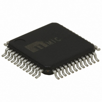
KSZ8041FTLI Micrel Inc, KSZ8041FTLI Datasheet - Page 6

KSZ8041FTLI
Manufacturer Part Number
KSZ8041FTLI
Description
Physical Layer Transceiver 10/100BASE-FX ( )
Manufacturer
Micrel Inc
Type
Transceiverr
Datasheet
1.KSZ8041MLLI.pdf
(65 pages)
Specifications of KSZ8041FTLI
Number Of Drivers/receivers
1/1
Protocol
SMII
Voltage - Supply
3.135 V ~ 3.465 V
Mounting Type
Surface Mount
Package / Case
48-TQFP, 48-VQFP
Lead Free Status / RoHS Status
Lead free / RoHS Compliant
For Use With
576-3294 - BOARD EVALUATION KSZ8041FTL
Lead Free Status / RoHS Status
Compliant, Lead free / RoHS Compliant
Other names
576-3347
Available stocks
Company
Part Number
Manufacturer
Quantity
Price
Company:
Part Number:
KSZ8041FTLI
Manufacturer:
MICREL
Quantity:
5 000
Part Number:
KSZ8041FTLI-TR
Manufacturer:
MICROCHIP/微芯
Quantity:
20 000
Micrel, Inc.
KSZ8041TL/FTL/MLL
List of Figures
Figure 1. Auto-Negotiation Flow Chart................................................................................................................................. 24
Figure 2. SMII Transmit Data/Control Segment................................................................................................................... 30
Figure 3. SMII Receive Data/Control Segment.................................................................................................................... 31
Figure 4. Typical Straight Cable Connection ....................................................................................................................... 32
Figure 5. Typical Crossover Cable Connection ................................................................................................................... 33
Figure 6. 25MHz Crystal / Oscillator Reference Clock for MII Mode ................................................................................... 35
Figure 7. 50MHz Oscillator Reference Clock for RMII Mode............................................................................................... 35
Figure 8. 125MHz Oscillator Reference Clock for SMII Mode ............................................................................................. 35
Figure 9. KSZ8041TL/FTL/MLL Power and Ground Connections....................................................................................... 36
Figure 10. KSZ8041TL/MLL and KSZ8041FTL Back-to-Back Media Converter................................................................. 38
Figure 11. MII SQE Timing (10Base-T) ............................................................................................................................... 50
Figure 12. MII Transmit Timing (10Base-T) ......................................................................................................................... 51
Figure 13. MII Receive Timing (10Base-T) .......................................................................................................................... 52
Figure 14. MII Transmit Timing (100Base-TX)..................................................................................................................... 53
Figure 15. MII Receive Timing (100Base-TX)...................................................................................................................... 54
Figure 16. RMII Timing – Data Received from RMII ............................................................................................................ 55
Figure 17. RMII Timing – Data Input to RMII ....................................................................................................................... 55
Figure 18. SMII Timing – Data Received from SMII ............................................................................................................ 56
Figure 19. SMII Timing – Data Input to SMII........................................................................................................................ 56
Figure 20. Auto-Negotiation Fast Link Pulse (FLP) Timing ................................................................................................. 57
Figure 21. MDC/MDIO Timing.............................................................................................................................................. 58
Figure 22. Reset Timing....................................................................................................................................................... 59
Figure 23. Recommended Reset Circuit.............................................................................................................................. 60
Figure 24. Recommended Reset Circuit for Interfacing with CPU/FPGA Reset Output ..................................................... 60
Figure 25. Reference Circuits for LED Strapping Pins......................................................................................................... 61
December 2009
6
M9999-120909-1.2


