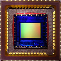
MT9V131C12STC Aptina LLC, MT9V131C12STC Datasheet - Page 7

MT9V131C12STC
Manufacturer Part Number
MT9V131C12STC
Description
SENSOR IMAGE VGA COLOR 48CLCC
Manufacturer
Aptina LLC
Series
Micron®DigitalClarity®r
Type
CMOS Imagingr
Datasheet
1.MT9V131C12STC.pdf
(14 pages)
Specifications of MT9V131C12STC
Package / Case
48-CLCC
Pixel Size
5.6µm x 5.6µm
Active Pixel Array
640H x 480V
Frames Per Second
15 ~ 90
Voltage - Supply
2.8V
Supply Voltage Range
2.55V To 3.05V
Operating Temperature Range
-20°C To +60°C
Digital Ic Case Style
CLCC
No. Of Pins
48
Supply Voltage Max
3.05V
Supply Voltage
RoHS Compliant
Ic Function
Digital Image Sensor
Rohs Compliant
Yes
Lead Free Status / RoHS Status
Lead free / RoHS Compliant
For Use With
557-1243 - KIT HEADBOARD FOR MT9V131557-1242 - KIT DEMO FOR MT9V131
Lead Free Status / RoHS Status
Lead free / RoHS Compliant
Other names
557-1241
Image Flow Processor
Overview of Architecture
Output and Formatting
PDF: 09005aef824c99b3/Source: 009005aef824c99bb
MT9V131_LDS_2.fm - Rev. B 3/07 EN
The image flow processor consists of a color processing pipeline and a measurement
and control logic block, as shown in Figure 6 on page 8. The stream of raw data from the
sensor enters the pipeline and undergoes a number of transformations. Image stream
processing starts from conditioning the black level and applying a digital gain. The lens
shading block compensates for signal loss caused by the lens. Next, the data is interpo-
lated to recover missing color components for each pixel and defective pixels are
corrected. The resulting interpolated RGB data passes through the current color correc-
tion matrix (CCM), gamma, and saturation corrections and is formatted for final output.
The measurement and control logic continuously accumulates statistics about image
brightness and color. Indoor 50/60Hz flicker is detected and automatically updated
when possible. Based on these measurements, the IFP calculates updated values for
exposure time and sensor analog gains, which are sent to the sensor core through the
communication bus.
Color correction is achieved through linear transformation of the image with a 3 x 3
color correction matrix. Color saturation can be adjusted in the range from zero (black
and white) to 1.25 (125% of full color saturation).
Gamma correction compensates for nonlinear dependence of the display device output
versus driving signal (monitor brightness versus CRT voltage).
Processed video can be output in the form of a progressive scan ITU_R BT.656 or RGB
stream. ITU_R BT.656 (default) stream contains 4:2:2 data with optional embedded
synchronization codes. This kind of output is typically suitable for subsequent display
by standard video equipment. For JPEG/MPEG compression, YUV/ encoding is suitable.
RGB functionality is provided to support LCD devices. The MT9V131 can be configured
to output 16-bit RGB (RGB565) and 15-bit RGB (RGB555), as well as two types of 12-bit
RGB (RGB444). The user can configure internal registers to swap odd and even bytes,
chrominance channels, and luminance and chrominance components to facilitate
interface to application processors.
MT9V131: 1/4-Inch SOC VGA CMOS Digital Image Sensor
7
Micron Technology, Inc., reserves the right to change products or specifications without notice.
Image Flow Processor
©2006 Micron Technology, Inc. All rights reserved.
Preliminary


