111MT80KPBF Vishay, 111MT80KPBF Datasheet - Page 4
111MT80KPBF
Manufacturer Part Number
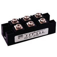
111MT80KPBF
Description
SCR Modules 800 Volt 110 Amp
Manufacturer
Vishay
Specifications of 111MT80KPBF
Mounting Style
Screw
Leaded Process Compatible
Yes
Package / Case
INT-A-Pak
Lead Free Status / RoHS Status
Lead free / RoHS Compliant


5.MT...KPbF, 9.MT...KPbF, 11.MT...KPbF Series
Vishay High Power Products
Note
• Table shows the increment of thermal resistance R
www.vishay.com
4
94353_01
94353_03a
ΔR CONDUCTION PER JUNCTION
DEVICES
5.MT...K
9.MT...K
11.MT...K
130
120
110
100
220
200
180
160
140
120
100
90
80
80
60
40
20
0
0
0
5.MT..K Series
T
~
J
Fig. 1 - Current Ratings Characteristic
5
= 125 °C
10
10
Total Output Current (A)
Total Output Current (A)
0.072
0.033
0.027
15
180°
20
20
25
(Rect.)
+
SINUSOIDAL CONDUCTION
-
120°
30
0.085
0.039
0.033
120°
30
AT T
35
(Rect.)
5.MT..K Series
40
120°
For technical questions, contact:
J
40
0.108
0.051
0.042
MAXIMUM
90°
45
50
50
Fig. 3 - Total Power Loss Characteristics
(Power Modules), 55 A to 110 A
Three Phase Controlled Bridge
0.152
0.069
0.057
thJC
60
55
60°
when devices operate at different conduction angles than DC
0.233
0.099
0.081
30°
94353_03b
94353_02
indmodules@vishay.com
0.055
0.027
0.023
180°
1000
100
220
200
180
160
140
120
100
10
80
60
40
20
0
1
RECTANGULAR CONDUCTION
0
0
Fig. 2 - Forward Voltage Drop Characteristics
0.091
0.044
0.037
120°
Instantaneous On-State Voltage (V)
AT T
1
Maximum Allowable Ambient
25
J
0.117
0.055
0.046
2
MAXIMUM
T
Temperature (°C)
90°
J
= 25 °C
50
3
0.157
0.071
0.059
60°
4
75
5.MT..K Series
Per junction
T
Document Number: 94353
J
5
= 125 °C
100
0.236
0.100
0.082
Revision: 13-Aug-08
30°
6
125
7
UNITS
K/W
Related parts for 111MT80KPBF
Image
Part Number
Description
Manufacturer
Datasheet
Request
R

Part Number:
Description:
357-036-542-201 CARDEDGE 36POS DL .156 BLK LOPRO
Manufacturer:
Vishay
Datasheet:
Part Number:
Description:
357-036-542-201 CARDEDGE 36POS DL .156 BLK LOPRO
Manufacturer:
Vishay
Datasheet:
Part Number:
Description:
357-036-542-201 CARDEDGE 36POS DL .156 BLK LOPRO
Manufacturer:
Vishay
Datasheet:
Part Number:
Description:
357-036-542-201 CARDEDGE 36POS DL .156 BLK LOPRO
Manufacturer:
Vishay
Datasheet:
Part Number:
Description:
357-036-542-201 CARDEDGE 36POS DL .156 BLK LOPRO
Manufacturer:
Vishay
Datasheet:
Part Number:
Description:
357-036-542-201 CARDEDGE 36POS DL .156 BLK LOPRO
Manufacturer:
Vishay
Datasheet:
Part Number:
Description:
357-036-542-201 CARDEDGE 36POS DL .156 BLK LOPRO
Manufacturer:
Vishay
Datasheet:
Part Number:
Description:
357-036-542-201 CARDEDGE 36POS DL .156 BLK LOPRO
Manufacturer:
Vishay
Datasheet:
Part Number:
Description:
357-036-542-201 CARDEDGE 36POS DL .156 BLK LOPRO
Manufacturer:
Vishay
Datasheet:
Part Number:
Description:
357-036-542-201 CARDEDGE 36POS DL .156 BLK LOPRO
Manufacturer:
Vishay
Datasheet:
Part Number:
Description:
357-036-542-201 CARDEDGE 36POS DL .156 BLK LOPRO
Manufacturer:
Vishay
Datasheet:
Part Number:
Description:
357-036-542-201 CARDEDGE 36POS DL .156 BLK LOPRO
Manufacturer:
Vishay
Datasheet:
Part Number:
Description:
357-036-542-201 CARDEDGE 36POS DL .156 BLK LOPRO
Manufacturer:
Vishay
Datasheet:
Part Number:
Description:
357-036-542-201 CARDEDGE 36POS DL .156 BLK LOPRO
Manufacturer:
Vishay
Datasheet:
Part Number:
Description:
357-036-542-201 CARDEDGE 36POS DL .156 BLK LOPRO
Manufacturer:
Vishay
Datasheet: