MCR72-003 ON Semiconductor, MCR72-003 Datasheet - Page 3
MCR72-003
Manufacturer Part Number
MCR72-003
Description
SCRs 100V 8A
Manufacturer
ON Semiconductor
Datasheet
1.MCR72-006.pdf
(7 pages)
Specifications of MCR72-003
Breakover Current Ibo Max
100 A
Rated Repetitive Off-state Voltage Vdrm
100 V
Off-state Leakage Current @ Vdrm Idrm
0.01 mA
Forward Voltage Drop
2 V
Gate Trigger Voltage (vgt)
1.5 V
Maximum Gate Peak Inverse Voltage
5 V
Gate Trigger Current (igt)
0.2 mA
Holding Current (ih Max)
6 mA
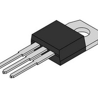
Mounting Style
Through Hole
Package / Case
TO-220-3
Lead Free Status / RoHS Status
Lead free / RoHS Compliant
Available stocks
Company
Part Number
Manufacturer
Quantity
Price
Company:

Part Number:
MCR72-003
Manufacturer:
ON
Quantity:
18 000


2. Ratings apply for negative gate voltage or R
3. R
THERMAL CHARACTERISTICS
ELECTRICAL CHARACTERISTICS
OFF CHARACTERISTICS
ON CHARACTERISTICS
DYNAMIC CHARACTERISTICS
Thermal Resistance, Junction−to−Case
Thermal Resistance, Junction−to−Ambient
Maximum Lead Temperature for Soldering Purposes 1/8 from Case for 10 Secs
Peak Repetitive Forward or Reverse Blocking Current (Note 2)
High Logic Level Supply Current from V
Peak Forward On-State Voltage
Gate Trigger Current (Continuous dc) (Note 3)
Gate Trigger Voltage (Continuous dc) (Note 3)
Gate Non−Trigger Voltage
Holding Current
Gate Controlled Turn-On Time
Critical Rate-of-Rise of Off-State Voltage
on the anode. Devices should not be tested with a constant current source for forward and reverse blocking capability such that the
voltage applied exceeds the rated blocking voltage.
(V
(I
(V
(V
(V
(V
(V
(V
GK
TM
AK
D
D
D
D
D
D
current not included in measurement.
= 12 V, R
= 12 V, R
= 12 Vdc, R
= 12 V, Initiating Current = 200 mA, R
= Rated V
= Rated V
= 16 A Peak, Pulse Width p 1 ms, Duty Cycle p 2%)
= Rated V
L
L
DRM
DRM
DRM
= 100 W)
= 100 W)
L
= 100 W, T
, I
, R
or V
TM
GK
= 16 A, I
RRM
= 1 kW, T
; R
J
= 110 C)
Characteristic
Characteristic
GK
G
J
= 2 mA)
= 1 kW)
= 110 C, Exponential Waveform)
CC
(T
C
= 25 C unless otherwise noted.)
GK
GK
= 1 kW)
= 1 kW. Devices shall not have a positive gate voltage concurrently with a negative voltage
http://onsemi.com
T
T
3
J
J
= 25 C
= 110 C
I
DRM
Symbol
Symbol
R
dv/dt
R
I
V
V
V
CCH
I
T
t
GT
I
qJC
qJA
, I
TM
GD
GT
gt
H
L
RRM
Min
0.1
−
−
4
−
−
−
−
−
−
Max
Typ
260
2.2
1.7
0.5
1.0
60
30
10
−
−
4
−
−
Max
500
200
2.0
1.5
6.0
mA
10
−
−
−
Unit
Unit
V/ms
C/W
C/W
mA
mA
mA
mA
mA
ms
V
V
V
C
Related parts for MCR72-003
Image
Part Number
Description
Manufacturer
Datasheet
Request
R

Part Number:
Description:
THYRISTOR SCR 8A 400V TO220AB
Manufacturer:
ON Semiconductor
Datasheet:

Part Number:
Description:
SCRs 400V 8A
Manufacturer:
ON Semiconductor
Datasheet:
Part Number:
Description:
THYRISTOR SCR 8A 400V TO220AB
Manufacturer:
ON Semiconductor
Datasheet:
Part Number:
Description:
THYRISTOR SCR 8A 600V TO220AB
Manufacturer:
ON Semiconductor
Datasheet:
Part Number:
Description:
THYRISTOR SCR 8A 100V TO-220AB
Manufacturer:
ON Semiconductor
Datasheet:
Part Number:
Description:
THYRISTOR SCR 8A 600V TO220AB
Manufacturer:
ON Semiconductor
Datasheet:
Part Number:
Description:
THYRISTOR SCR 8A 400V TO220AB
Manufacturer:
ON Semiconductor
Datasheet:
Part Number:
Description:
SCRs 600V 8A
Manufacturer:
ON Semiconductor
Datasheet:
Part Number:
Description:
SCRs 600V 8A
Manufacturer:
ON Semiconductor
Datasheet:

Part Number:
Description:
SENSITIVE GATE SILICON CONTROLLED RECTIFIERS
Manufacturer:
ONSEMI [ON Semiconductor]
Datasheet:

Part Number:
Description:
ON Semiconductor [VOLTAGE REGULATOR]
Manufacturer:
ON Semiconductor
Datasheet:
Part Number:
Description:
357-036-542-201 CARDEDGE 36POS DL .156 BLK LOPRO
Manufacturer:
ON Semiconductor
Datasheet:
Part Number:
Description:
357-036-542-201 CARDEDGE 36POS DL .156 BLK LOPRO
Manufacturer:
ON Semiconductor
Datasheet:
Part Number:
Description:
357-036-542-201 CARDEDGE 36POS DL .156 BLK LOPRO
Manufacturer:
ON Semiconductor
Datasheet:
Part Number:
Description:
357-036-542-201 CARDEDGE 36POS DL .156 BLK LOPRO
Manufacturer:
ON Semiconductor
Datasheet: