G2R-1A-E-AC120 Omron, G2R-1A-E-AC120 Datasheet - Page 24
G2R-1A-E-AC120
Manufacturer Part Number
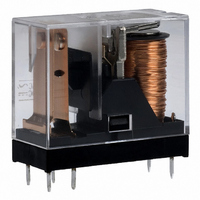
G2R-1A-E-AC120
Description
RELAY
Manufacturer
Omron
Series
G2Rr
Specifications of G2R-1A-E-AC120
Relay Type
General Purpose
Contact Form
SPST-NO (1 Form A)
Contact Rating (current)
16A
Switching Voltage
380VAC, 125VDC - Max
Coil Type
Standard
Coil Current
7.5mA
Coil Voltage
120VAC
Turn On Voltage (max)
96 VAC
Turn Off Voltage (min)
36 VAC
Mounting Type
Through Hole
Termination Style
PC Pin
Circuit
SPST-NO (1 Form A)
Contact Rating @ Voltage
16A @ 250VAC
Control On Voltage (max)
96 VAC
Control Off Voltage (min)
36 VAC
Contact Rating
16 A
Contact Termination
Solder Pin
Mounting Style
Through Hole
Power Consumption
0.9 VA
Contact Material
Silver Alloy
Coil Resistance
6.5 K Ohms
Lead Free Status / RoHS Status
Lead free / RoHS Compliant
Lead Free Status / RoHS Status
Lead free / RoHS Compliant
Other names
G2R-1A-E-AC120
G2R1AEAC120
Z2310
G2R1AEAC120
Z2310
Available stocks
Company
Part Number
Manufacturer
Quantity
Price
Company:

Part Number:
G2R-1A-E-AC120
Manufacturer:
ASTEC
Quantity:
200


■ Driving by IC
An IC on which multiple driving transistors are integrated is available.
The designing of the circuit or PCB to drive multiple relays, a small-
size solenoid, or a small-size lamp can be simplified by using this IC.
Consult the manufacturer of the IC for details. For V
description of the related voltage and surge suppressor.
Dimensions Connection (Top view)
Equivalent circuit
■ Driving by TTL
TTLs can be divided into two types by classification of the output:
totem-pole and open-collector outputs. Connection of each type of
TTL is described below.
Use a diode as surge suppressor.
In the specifications of some ICs, such a phrase as “fan-out 10” may
be used in place of the legend I
TTLs can be connected in parallel. In terms of current, fan-out 1
equals 1.6 mA. Hence,
Fan-out n = 1.6 x n (mA)
1. To drive a relay by the totem-pole output of a TTL, these condi-
24
tions must be satisfied:
• I
• I
• Minimum supply voltage (4.75 V) – Maximum V
resistance.
(%)/Coil resistance
put voltage) > Lower-limit value of pickup voltage (Refer to Driv-
ing by Transistor)
OL
OH
(high-level output current) < Rated current x pickup voltage
(low-level output current) > Maximum supply voltage/Coil
Electromechanical Relays
GND
OL
. This denotes that 10 standard
I: Input (Base)
O: Output (Collector)
GND: (Common Emitter)
Technical Information
OL
GND
CE
(low-level out-
, refer to the
Totem-pole output
2. To drive a relay with open-collector output type TTL, a degree of
Open-collector output
The above description of the standard TTL is applicable when using
S, H, and LS type TTLs.
■ Driving by Other Switching
Consult the manufacturer of the switching device. The upper- and
lower-limit values of the pickup voltage can be determined in the
same manner as described in Upper-limit Pickup Voltage and Lower-
limit Pickup Voltage.
Example of Driving by SCR
freedom is allowed in the ratings of the relay coil. However, these,
conditions must be satisfied:
• I
• I
• V
• V
Devices
by Transistor.)
to Driving by Transistor.)
OL
OH
O
OL
> Maximum supply voltage to the relay coil/Coil resistance
= Dielectric strength of the output transistor (Refer to Driving
< Rated current x pickup voltage (%)/200
= Collector emitter voltage V
CE
of the output transistor (Refer
Related parts for G2R-1A-E-AC120
Image
Part Number
Description
Manufacturer
Datasheet
Request
R

Part Number:
Description:
RELAY
Manufacturer:
Omron
Datasheet:

Part Number:
Description:
RELAY
Manufacturer:
Omron
Datasheet:
Part Number:
Description:
RELAY
Manufacturer:
Omron
Datasheet:
Part Number:
Description:
RELAY
Manufacturer:
Omron
Datasheet:

Part Number:
Description:
RELAY
Manufacturer:
Omron
Datasheet:
Part Number:
Description:
RELAY
Manufacturer:
Omron
Datasheet:
Part Number:
Description:
RELAY
Manufacturer:
Omron
Datasheet:
Part Number:
Description:
RELAY
Manufacturer:
Omron
Datasheet:
Part Number:
Description:
RELAY
Manufacturer:
Omron
Datasheet:
Part Number:
Description:
RELAY
Manufacturer:
Omron
Datasheet:
Part Number:
Description:
RELAY
Manufacturer:
Omron
Datasheet:
Part Number:
Description:
RELAY
Manufacturer:
Omron
Datasheet:
Part Number:
Description:
RELAY PWR SPST 16A 24VDC PCB
Manufacturer:
Omron
Datasheet:
Part Number:
Description:
RELAY
Manufacturer:
Omron
Datasheet:
Part Number:
Description:
RELAY
Manufacturer:
Omron
Datasheet: