G6JU-2FL-Y-TR DC3 Omron, G6JU-2FL-Y-TR DC3 Datasheet - Page 10
G6JU-2FL-Y-TR DC3
Manufacturer Part Number
G6JU-2FL-Y-TR DC3
Description
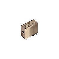
SMT Tape & Reel Latching Relay
Manufacturer
Omron
Series
G6J-Yr
Datasheet
1.G6J-2FL-Y-TR_DC24.pdf
(12 pages)
Specifications of G6JU-2FL-Y-TR DC3
Relay Type
Telecom
Circuit
DPDT (2 Form C)
Contact Rating @ Voltage
1A @ 30VDC
Coil Type
Latching, Single Coil
Coil Current
33.7mA
Coil Voltage
3VDC
Control On Voltage (max)
2.25 VDC
Mounting Type
Surface Mount
Termination Style
Gull Wing
Contact Form
2 Form C
Power Consumption
100 mW
Lead Free Status / RoHS Status
Lead free / RoHS Compliant
Control Off Voltage (min)
-
Lead Free Status / Rohs Status
Lead free / RoHS Compliant
Other names
G6JU-2FL-Y-TRDC3
G6JU2FLYTRDC3
G6JU2FLYTRDC3


Precautions
Correct Use
Long Term Current Carrying
Under a long-term current carrying without switching, the insulation
resistance of the coil goes down gradually due to the heat generated
by the coil itself. Furthermore, the contact resistance of the Relay will
gradually become unstable due to the generation of film on the con-
tact surfaces. A Latching Relay can be used to prevent these prob-
lems. When using a non-latching relay, the design of the fail-safe
circuit provides protection against contact failure and open coils.
Handling of Surface-mounting Relays
Use the Relay as soon as possible after opening the moisture-proof
package. If the Relay is left for a long time after opening the mois-
ture-proof package, the appearance may suffer and seal failure may
occur after the solder mounting process. To store the Relay after
opening the moisture-proof package, place it into the original pack-
age and seal the package with adhesive tape.
When washing the product after soldering the Relay to a PCB, use a
water-based solvent or alcohol-based solvent, and keep the solvent
temperature at less than 40°C. Do not put the relay in a cold cleaning
bath immediately after soldering.
Soldering
Solder: JIS Z3282, H63A
Soldering temperature: Approx. 250°C (At 260°C if the DWS method
is used.)
Soldering time: Approx. 5 s max. (Approx. 2 s for the first time and
approx. 3 s for the second time if the DWS method is used.)
Be sure to adjust the level of the molten solder so that the solder will
not overflow onto the PCB.
Claw Securing Force During Automatic Insertion
During automatic insertion of Relays, make sure to set the securing
force of the claws to the following values so that the Relay character-
istics will be maintained.
Environmental Conditions During Operation, Storage,
Protect the Relays from direct sunlight and keep the Relays under
normal temperature, humidity, and pressure.
Mounting Latching Relays
The Latching Relays are reset before shipping. If excessive vibration
or shock is imposed, however, the Latching Relays may be set acci-
dentally. Be sure to apply a reset signal before use. Make sure that
the vibration or shock that is generated by other devices on the same
panel does not exceed the rated value of the Latching Relays.
66
Do not attach them to the center area or to only part of the Relay.
and Transportation
Secure the claws to the area indicated by shading.
Surface-mounting Relay
Direction A: 4.90 N max.
Direction B: 9.80 N max.
Direction C: 9.80 N max.
A
C
B
G6J-Y
Maximum Voltage
The maximum voltage of the coil can be obtained from the coil tem-
perature increase and the heat-resisting temperature of coil insulat-
ing sheath material. (Exceeding the heat-resisting temperature may
result in burning or short-circuiting.) The maximum voltage also
involves important restrictions. Maximum voltage:
• must not cause thermal changes or deterioration of the insulating
• must not cause damage to other control devices.
• must not cause any harmful effect on people.
• must not cause fire.
Therefore, be sure not to exceed the maximum voltage specified in
the catalog.
As a rule, the rated voltage must be applied to the coil. A voltage
exceeding the rated value, however, can be applied to the coil pro-
vided that the voltage is less than the maximum voltage. It must be
noted that continuous voltage application to the coil will cause a coil
temperature increase which could deteriorate the coil insulation,
shorten the relay’s electrical life, or affect various characteristics of
the relay.
Coating
Relays mounted on PCBs may be coated or washed. Do not apply
coatings or detergents containing silicone.
Other Handling
Dropping the relay may impose excess shock that exceeds the spec-
ifications. Do not use any relay that has been dropped.
material.
Related parts for G6JU-2FL-Y-TR DC3
Image
Part Number
Description
Manufacturer
Datasheet
Request
R

Part Number:
Description:
RELAY LATCH DPDT 1A 5VDC SMD
Manufacturer:
Omron
Datasheet:
Part Number:
Description:
RELAY LATCH DPDT 1A 4.5VDC SMD
Manufacturer:
Omron
Datasheet:
Part Number:
Description:
RELAY LATCH DPDT 1A 24VDC SMD
Manufacturer:
Omron
Datasheet:
Part Number:
Description:
RELAY LATCH DPDT 1A 12VDC SMD
Manufacturer:
Omron
Datasheet:

Part Number:
Description:
SMT Tape & Reel Latching Relay
Manufacturer:
Omron
Datasheet:

Part Number:
Description:
Low Signal Latching SMT Relay
Manufacturer:
Omron
Datasheet:
Part Number:
Description:
SIGNAL RELAY, DPDT, 12VDC, 1A, SMD
Manufacturer:
Omron
Datasheet:
Part Number:
Description:
SIGNAL RELAY, DPDT, 24VDC, 1A, SMD
Manufacturer:
Omron
Datasheet:
Part Number:
Description:
SIGNAL RELAY, DPDT, 4.5VDC, 1A, SMD
Manufacturer:
Omron
Datasheet:
Part Number:
Description:
SIGNAL RELAY, DPDT, 5VDC, 1A, SMD
Manufacturer:
Omron
Datasheet:
Part Number:
Description:
Low Signal Relays - PCB DPDT 1-Coil 3 VDC 1A 100mW Latch Long
Manufacturer:
Omron
Datasheet: