S1MA-E3/61T Vishay, S1MA-E3/61T Datasheet - Page 3
S1MA-E3/61T
Manufacturer Part Number
S1MA-E3/61T
Description
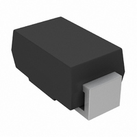
DIODE GPP 1A 1000V SMA DO-214AC
Manufacturer
Vishay
Datasheet
1.S1BA-E35AT.pdf
(4 pages)
Specifications of S1MA-E3/61T
Diode Type
Standard
Voltage - Forward (vf) (max) @ If
1.1V @ 1A
Voltage - Dc Reverse (vr) (max)
1000V (1kV)
Current - Average Rectified (io)
1A
Current - Reverse Leakage @ Vr
3µA @ 1000V
Speed
Standard Recovery >500ns, > 200mA (Io)
Reverse Recovery Time (trr)
1µs
Mounting Type
Surface Mount
Package / Case
DO-214AC, SMA
Product
Ultra Fast Recovery Rectifier
Configuration
Single
Reverse Voltage
1 KV
Forward Voltage Drop
1.1 V
Recovery Time
1 us
Forward Continuous Current
1 A
Max Surge Current
30 A
Reverse Current Ir
3 uA
Mounting Style
SMD/SMT
Maximum Operating Temperature
+ 150 C
Minimum Operating Temperature
- 55 C
Repetitive Reverse Voltage Vrrm Max
1kV
Forward Current If(av)
1A
Forward Voltage Vf Max
861mV
Reverse Recovery Time Trr Max
1µs
Forward Surge Current Ifsm Max
30A
Lead Free Status / RoHS Status
Lead free / RoHS Compliant
Capacitance @ Vr, F
-
Lead Free Status / Rohs Status
Lead free / RoHS Compliant
Other names
S1MA-E3/5AT
Available stocks
Company
Part Number
Manufacturer
Quantity
Price
Company:

Part Number:
S1MA-E3/61T
Manufacturer:
Vishay Semiconductors
Quantity:
6 164


PACKAGE OUTLINE DIMENSIONS in inches (millimeters)
Document Number: 88711
Revision: 07-Apr-08
0.001
Figure 3. Typical Instantaneous Forward Characteristics
0.01
0.01
100
0.1
0.1
10
10
Figure 4. Typical Reverse Leakage Characteristics
1
1
0.4
0
Percent of Rated Peak Reverse Voltage (%)
Instantaneous Forward Voltage (V
20
0.8
0.065 (1.65)
0.049 (1.25)
T
0.060 (1.52)
0.030 (0.76)
J
0.090 (2.29)
0.078 (1.98)
= 125 °C
40
PDD-Americas@vishay.com, PDD-Asia@vishay.com, PDD-Europe@vishay.com
T
For technical questions within your region, please contact one of the following:
1.2
T
J
J
T
= 25 °C
Pulse Width = 300 µs
1 % Duty Cycle
= 25 °C
J
= 75 °C
60
DO-214AC (SMA)
1.6
80
0.177 (4.50)
0.157 (3.99)
0.208 (5.28)
0.194 (4.93)
Cathode Band
)
0.008 (0.203)
0 (0)
100
2.0
0.110 (2.79)
0.100 (2.54)
0.012 (0.305)
0.006 (0.152)
1000
0.066 (1.68)
100
100
0.060 (1.52)
10
10
MIN.
1
1
0.01
0.01
MIN.
Figure 6. Typical Transient Thermal Impedance
Mounting Pad Layout
Vishay General Semiconductor
Figure 5. Typical Junction Capacitance
0.1
0.1
(5.28) REF.
t - Pulse Duration (s)
Reverse Voltage (V)
0.208
S1(K, M)
Units Mounted on
0.20 x 0.20" (5.0 x 5.0 mm)
x 0.5 mil. Inches (0.013 mm)
Thick Copper Land Areas
1
1
0.074 (1.88)
MAX.
S1A thru S1M
T
f = 1.0 MHz
V
S1(A - J)
J
sig
= 25 °C
10
10
= 50 mVp-p
www.vishay.com
100
100
3
Related parts for S1MA-E3/61T
Image
Part Number
Description
Manufacturer
Datasheet
Request
R

Part Number:
Description:
1A,1000V,GPP,STD,SM RECT
Manufacturer:
Vishay
Datasheet:

Part Number:
Description:
357-036-542-201 CARDEDGE 36POS DL .156 BLK LOPRO
Manufacturer:
Vishay
Datasheet:
Part Number:
Description:
357-036-542-201 CARDEDGE 36POS DL .156 BLK LOPRO
Manufacturer:
Vishay
Datasheet:
Part Number:
Description:
357-036-542-201 CARDEDGE 36POS DL .156 BLK LOPRO
Manufacturer:
Vishay
Datasheet:
Part Number:
Description:
357-036-542-201 CARDEDGE 36POS DL .156 BLK LOPRO
Manufacturer:
Vishay
Datasheet:
Part Number:
Description:
357-036-542-201 CARDEDGE 36POS DL .156 BLK LOPRO
Manufacturer:
Vishay
Datasheet:
Part Number:
Description:
357-036-542-201 CARDEDGE 36POS DL .156 BLK LOPRO
Manufacturer:
Vishay
Datasheet:
Part Number:
Description:
357-036-542-201 CARDEDGE 36POS DL .156 BLK LOPRO
Manufacturer:
Vishay
Datasheet:
Part Number:
Description:
357-036-542-201 CARDEDGE 36POS DL .156 BLK LOPRO
Manufacturer:
Vishay
Datasheet:
Part Number:
Description:
357-036-542-201 CARDEDGE 36POS DL .156 BLK LOPRO
Manufacturer:
Vishay
Datasheet:
Part Number:
Description:
357-036-542-201 CARDEDGE 36POS DL .156 BLK LOPRO
Manufacturer:
Vishay
Datasheet:
Part Number:
Description:
357-036-542-201 CARDEDGE 36POS DL .156 BLK LOPRO
Manufacturer:
Vishay
Datasheet:
Part Number:
Description:
357-036-542-201 CARDEDGE 36POS DL .156 BLK LOPRO
Manufacturer:
Vishay
Datasheet:
Part Number:
Description:
357-036-542-201 CARDEDGE 36POS DL .156 BLK LOPRO
Manufacturer:
Vishay
Datasheet:
Part Number:
Description:
357-036-542-201 CARDEDGE 36POS DL .156 BLK LOPRO
Manufacturer:
Vishay
Datasheet: