A22E-MP-11 Omron, A22E-MP-11 Datasheet - Page 16
A22E-MP-11
Manufacturer Part Number
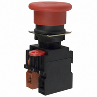
A22E-MP-11
Description
Non-lighted,push-pull,1NC
Manufacturer
Omron
Series
A22r
Type
Emergency Stopr
Specifications of A22E-MP-11
Circuit
DPST (1-NO, 1-NC)
Switch Function
On-Off, Off-On
Contact Rating @ Voltage
10A @ 110VAC
Actuator Type
Mushroom Button
Mounting Type
Panel Mount
Termination Style
Screw Terminal
Contact Form
SPST - NC/NO
Contact Rating
10 Amps at 110 Volts
Actuator
Round, Medium
Mounting Style
Through Hole
Illumination
Not Illuminated
Body Shape
Square
Dielectric Strength
2500 Volts
Features
Easy mounting and removal of switch unit
Insulation Resistance
100 MOhms
Mounting Angle
Straight
Water / Moisture Rating
IP65
Contact Configuration
SPST-NO / SPST-NC
Switch Operation
Pushlock Turn Reset
Contact Voltage Ac Nom
440V
Contact Voltage Dc Nom
380V
Contact Current Max
10A
Actuator Style
Round
Lead Free Status / RoHS Status
Lead free / RoHS Compliant
Illumination Type, Color
-
Illumination Voltage (nominal)
-
Lead Free Status / Rohs Status
Lead free / RoHS Compliant
Other names
A22EMP11
Z1507
Z1507


Installing/Removing the Switch Blocks
Safety Precautions
Be sure to read the precautions for all pushbutton switches in the Pushbutton Switches Group Catalog (Cat. No. X032).
Do not apply a voltage exceeding the rated voltage across
the incandescent lamp terminals.
The lamp may be destroyed and the operation unit may fly
out.
If the Operation Unit is separated from the Socket Unit, the
equipment will not stop, creating a hazardous condition.
Secure the lever on the Socket Unit by using the
A22Z-3380 Lock Plate so that the Operation Unit cannot
be easily separated from the Socket Unit.
(Refer to “Mounting the Lock Plate” at the right.)
• Hook the small protrusion on the Mounting Latch
into the groove on the other side of the lever, then
push up the Switch Block in the direction indicated
by the arrow in the figure below.
Mounting
(1) Installing the Switch Blocks
Latch
Switch block
!CAUTION
Protrusion
Lever
• Insert a screwdriver between the Mounting Latch
and the Switch Block, then push down the
screwdriver in the direction indicated by the arrow
in the following figure.
Use either of the following screwdrivers.
Flat-head screwdriver
Phillips screwdriver
(2) Removing the Switch Blocks
3 to 6 mm dia.
3 to 6 mm
Mounting
Mounting the Lock Plate
1. Confirm that the lever on the Mounting Latch is on the side where
2. Press the hole on the Lock Plate onto the protrusion on the
• Always make sure that the power is turned OFF before wiring the
• Do not tighten the mounting ring more than necessary using tools
• Recommended panel thickness: 1 to 5 mm.
• When mounting the caps after changing the LED or the caps,
Operation
Unit
Switch. Also, do not touch the terminals or other current-carrying
ports while power is being supplied. Electric shock may occur.
such as pointed-nose pliers. Doing so will damage the mounting
ring. The tightening torque is 0.98 to 1.96 N·m.
tighten the caps at a tightening torque of 0.49 tp 0.78 N·m.
the Operation Unit is secured and then insert the protrusion on the
Lock Plate into the hole in the lever on the Mounting Latch.
Mounting Latch until it clicks into place.
Screwdriver
Mounting Latch
Lever
Precautions for Correct Use
1
• Loosen the terminal screw from the Switch
Unit until it completely comes off the groove,
insert a screwdriver as shown in the following
figure, then push up the washer in the
direction indicated by the arrow to temporarily
secure it.
Now, a round crimp terminal can be
connected. After inserting the terminal, tighten
the screws to complete wiring.
Screw
Washer
Lock Plate
Wiring
Screwdriver
A22E
2
16
Related parts for A22E-MP-11
Image
Part Number
Description
Manufacturer
Datasheet
Request
R

Part Number:
Description:
Non-lighted,pushpull,1NC,40dia
Manufacturer:
Omron
Datasheet:

Part Number:
Description:
ESTOP OP UNIT 40mm P-P
Manufacturer:
Omron
Datasheet:
Part Number:
Description:
Non-lighted,push-pull,2NC
Manufacturer:
Omron
Datasheet:

Part Number:
Description:
Non-lighted,push-lock,turnrese
Manufacturer:
Omron
Datasheet:
Part Number:
Description:
SWITCH, EMERGENCY STOP, SPST-NC, 440VAC
Manufacturer:
Omron
Datasheet:

Part Number:
Description:
Non-lighted,push-lock,turnrese
Manufacturer:
Omron
Datasheet:
Part Number:
Description:
Non-lighted,push-lock,turnrese
Manufacturer:
Omron
Datasheet:
Part Number:
Description:
ESTOP OP UNIT 40mm P-L,T-R
Manufacturer:
Omron
Datasheet:

Part Number:
Description:
Non-lighted,push-lock,turnrese
Manufacturer:
Omron
Datasheet:
Part Number:
Description:
Non-lighted,push-lock,turnrest
Manufacturer:
Omron
Datasheet:
Part Number:
Description:
SWITCH PB RND MOM SPST-NO/NC RED
Manufacturer:
Omron
Datasheet:

Part Number:
Description:
SWITCH PB ROUND ALT SPST-NO BLUE
Manufacturer:
Omron
Datasheet:

Part Number:
Description:
SWITCH PB ROUND ALT SPST-NO BLK
Manufacturer:
Omron
Datasheet:

Part Number:
Description:
SWITCH PB ROUND ALT SPST-NO GRN
Manufacturer:
Omron
Datasheet:

Part Number:
Description:
SWITCH PB ROUND ALT SPST-NO RED
Manufacturer:
Omron
Datasheet: