88 865 115 Crouzet USA, 88 865 115 Datasheet - Page 12
88 865 115
Manufacturer Part Number
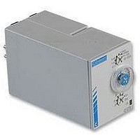
88 865 115
Description
Electromechanical Multifunction Timer
Manufacturer
Crouzet USA
Datasheet
1.88_865_385.pdf
(12 pages)
Specifications of 88 865 115
Time Range
0.1 Sec. To 100 Hr.
Power Consumption
1.5W
Reset Time
100ms
Supply Voltage Ac, Max
240V
Mounting Type
DIN Mount
Time Range Min
0.1s
Supply Voltage Min
24V
Contact Configuration
SPCO
Nom Input Voltage
240VAC
Delay Time Range
0.1sec To 100hr
Relay Mounting
DIN Rail
Adjustment Type
Screwdriver Slot
Coil Voltage Vdc Nom
24V
Contact Current Ac Max
8A
Rohs Compliant
Yes
Signal Input Type
Volt-Free Contact
Supply Current
10A
Lead Free Status / RoHS Status
Lead free / RoHS Compliant


Function K
Delay on de-energisation - true delay OFF
On energisation, the output changes state.
On de–energisation timing commences and
the output only returns to the
reset condition after timing.
Function L
Cyclic timing - Asymmetrical recycler
Repetitive cycle comprising 2 independent
adjustable time bases. Each time base corresponds
alternately to a different output state.
N.B. : The cycle starts with the
output in the rest position.
Function Li
Cyclic timing - Asymmetrical recycler
Repetitive cycle comprising 2 independent
adjustable time bases. Each time base corresponds
alternately to a different output state.
N.B. : The cycle starts with the output
in the operating position.
Function N
"Safe-guard"
At the first control pulse the output is energised.
To complete the timing the interval between
the two control pulses must be greater than the timing set.
Function O
"Delayed safe-guard"
On energisation, a first timing sequence
occurs and the output changes state.
With the closing of the control contact,
the output resets and the timing starts, with
the output being activated after timing.
For the timing to be completed, the interval
between the closing of two control contacts
must be greater than the timing set.
Function P
Delayed fixed-length pulse
Timing begins on energisation. At the end
of the timing period output relay R (or the load)
changes state for a period of approx. 500 milliseconds.
Our timers are designed according to international recommendations (IEC),
American (UL), Canadian (CSA) and German (VDE) standards, European
standards (EN), etc.
Proof of compliance with these standards and recommendations is
demonstrated by approval (a symbol or certificate of conformity granted by an
accredited body) or by the manufacturer's declaration of conformity (drafted in
accordance with ISO/IEC 22 guidelines).
We have indicated the principal approvals so far obtained in the table below.
Conformity to standards is indicated in the "technical characteristics".
Machine safety
Our products are compatible with standard EN 60204-1 (IEC 201-1)
concerning the safety of electrical equipment for machinery.
STANDARDS AND APPROVALS
2 relays timed or
1 relay timed and 1 instantaneous
2 relays timed or
1 relay timed and 1 instantaneous
2 relays timed or
1 relay timed and 1 instantaneous
R1/R2
R1/R2
FUNCTION DIAGRAMS FOR TIMERS
U
C
R
U
C
R
R1
R2
1 relay
U
R
U
U
R
U
R
1 relay
U
R
U
1 relay
U
T
T1
T1
T1
∞
T1
∞
T
T2
T2
T2
T2
T
P = 500 ms
∞
P
T
T
T
T
∞
73
Function Pt
Delayed fixed length pulse (with memory)
As function P but with memory
Function Q
Star-delta
At the end of timing, the output is not
energised. It remains "open" (not conducting)
and will only change state after the fixed
time of Ti has elapsed.
Dwell time selectable
Function T
Timing on energisation with memory
a - energisation by control signal
The timer sums the times for which the
control contact is closed (C1).
Reset is by the reset signal (C2) only.
b - energisation by supply voltage
The timer sums the times for which
the supply voltage (U) is on.
Reset is by the reset signal (C2) only.
Function T
Latching relay by control contact
After energisation, closure of the control
contact causes output relay R to energise.
A second closure of control contact
de–energises the relay.
Function Tt
Timed latching relay by control contact
As function T
contact does not occur before end of time
period, the relay will de–energise at the end
of the time period.
Function W
Timing after pulse on control contact
After energisation, if the control contact
opens it causes output relay R (or the load)
to change state and timing to start.
At the end of the timing period,
relay R resets to its original state.
Switzerland Canada
National approvals
L
L
but if second closure of control
APPROVAL MARKINGS
United States
UL
France
U
C
R
1 relay
1 relay
U
C
R
U
C
R
1 relay
U
C
R
Germany
(
VDE
1
TIMERS
Conformity
T= ( )
T
T
(
2 - P
+ 12
T
Related parts for 88 865 115
Image
Part Number
Description
Manufacturer
Datasheet
Request
R

Part Number:
Description:
TIMER, MULTIFUNCTION
Manufacturer:
Crouzet USA
Datasheet:

Part Number:
Description:
Electromechanical Multifunction Timer
Manufacturer:
Crouzet USA
Datasheet:

Part Number:
Description:
MULTI-FUNCTION TIMER, DPDT, 100H, 230VAC
Manufacturer:
Crouzet USA
Datasheet:
Part Number:
Description:
TIMER, MULTIFUNCTION
Manufacturer:
Crouzet USA
Datasheet:
Part Number:
Description:
TIMER, FLIP/FLOP
Manufacturer:
Crouzet USA
Datasheet:

Part Number:
Description:
TIMER, CAGE CLAMP, MURC3
Manufacturer:
Crouzet USA
Datasheet:

Part Number:
Description:
LAMP, INCAND, BAYONET, 6.8V, 12.98W
Manufacturer:
SPC TECHNOLOGY
Datasheet:

Part Number:
Description:
Circular MIL / Spec Connectors JT Series MIL-DTL-38999 II
Manufacturer:
Amphenol

Part Number:
Description:
M3 DISPLAY KIT, 12 I/O, 230VAC
Manufacturer:
Crouzet USA
Datasheet:
Part Number:
Description:
M3 DISPLAY KIT, 20 I/O, 24VDC
Manufacturer:
Crouzet USA
Datasheet:

Part Number:
Description:
Controller; CTD46 Dual Display Temperature, 1/16 DIN, NEMA 4X, 110/220VAC
Manufacturer:
Crouzet USA
Datasheet:

Part Number:
Description:
11R1084
Manufacturer:
Crouzet USA
Datasheet:
Part Number:
Description:
11R1086
Manufacturer:
Crouzet USA
Datasheet:
Part Number:
Description:
11R1087
Manufacturer:
Crouzet USA
Datasheet:
Part Number:
Description:
11R1089
Manufacturer:
Crouzet USA
Datasheet: