1
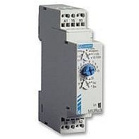
Chronos 2 electronic timers - 17.5 mm
1 changeover relay output
Non stocked, minimum order quantity 100 units.
Technical specifications
Timing
Repetition accuracy (with constant
parameters)
Drift
- Temperature
- Voltage
Display precision according to IEC 1812-1
Minimum pulse duration
- Typically (relay version)
- Typically (solid state version)
- Typically under load (relay version)
Maximum reset time by de-energisation
- Typically (relay version)
- Typically (solid state version)
Immunity to breaks in supply voltage: typically
Power supply
Multi-voltage power supply
Frequency
Operating range
Load factor
Maximum power consumption
Output elements relay output
1 or 2 changeover relays, AgNi (cadmium-free)
Rated power
Maximum breaking current
Minimum breaking current
Voltage breaking capacity
Electrical life
Mechanical life
Breakdown voltage acc. to IEC 1812-1
Impulse voltage acc. to IEC 664-1 IEC 1812-1
Display
State displayed by 1 LED
- Flashing green when on
Green LED operation indicator
- timer on, no timing in progress
- timing in progress
- Relay waiting, no timing in progress
Input type
- Volt-free contact
- 3-wire PNP output control option maximum
residual voltage: 0.4 V whatever the timer
power supply
(except functions Di-D and Li-L)
Multi-function or mono-function
Multi-range
Multi-voltage
1 changeover relay output: 8 A - 250 V (10 A UL)
Screw or spring terminals
1 LED status indicators
Option of connecting an external power supply to the
control input
3-wire sensor control option
Pulsing:
Flashing:
Permanently lit:
(
7 ranges, available options
Other information
± 0.5 %
(CEI 1812-1)
± 0.05 % / °C
± 0.2 % / V
±10 % / 25 °C
30 ms
50 ms
100 ms
100 ms
350 ms
>10 ms
depending on version,
see page 1/13
50/60 Hz
85 to 110 % Un
(85 to 120 % Un for
12V AC/DC)
100 %
0.6 W 24V AC/DC
1.5 W 230V AC
32 VA 230V AC
2000 VA / 80 W
2000 V A / 80W
8 A AC 8 A DC
10 mA / 5 VDC
250V AC/VDC
10
8 A 250V resistive
5 x 10
2.5 kV / 1min /
1 mA /50Hz
5 kV, wave 1.2 / 50 s
0.4 V
)
5
operations
6
operations
1/14
Timing
Types
Screw terminals
Spring terminals
Part numbers and voltage
24V c / 24 • 240V a
12 V a / c
12 • 240 V a / c
Functions
Nominal current
Timing ranges
1s - 10 s - 1 min - 10 min - 1 h - 10 h - 100 h
General specifications
Conforming to standards
IEC 1812-1, EN 50081-1/2, EN 50082-1/2, LV
directives (73/23/EEC + 93/68/EEC
(CE marking) + EMC (89/336/EEC +
IEC 669-2-3 (17.5 mm)
Approvals
UL - CSA - cUL pending
Temperatures limits
- use
- stored
Installation category (acc. to IEC 664-1)
Creepage distance and clearance acc. to
IEC 664-1
Degree of protection acc. to IEC 529
- terminal block
- casing
- front face (except Tk2R1)
Vibration resistance acc. to IEC 68-2-6
Relative humidity acc. to IEC 68-2-3
without condensation
Electromagnetic compatibility
- Immunity to electrostatic discharges acc. to
IEC 1000-42
- Immunity to electrostatic fields acc. to
ENV 50140/204 (IEC 1000-4-3)
- Immunity to rapid transient bursts acc. to IEC
1000-4-4
- Immunity to shock waves on power supply
acc. to IEC 1000-4-5
- Immunity to radiofrequency in common mode
acc. to ENV
- Immunity to voltage dips and breaks acc. to
IEC 1000-4-11
- Mains-borne and radiated emissions acc. to
EN 55022 (EN 55011 Group 1)
Fixing: Symmetrical DIN rail (EN 50022)
Connection capacity
- without ferrule
- with ferrule
Spring terminals, 2 terminals per
connection point
- flexible wire
- rigid wire
Casing material
Weight : 17.5 mm casing
(7 ranges)
0.1s • 100h
MUR1
88 826 105
Multi-function
A - At - B - C - H - Ht -
Di - D - Ac - Bw
8 A
-
-
-
0.1s • 100h
MAR1
88 826 115
Bifunction
A - At
8 A
-20 °C + 60 °C
-30 °C + 60 °C
Voltage surge
category
4 kV / 3
IP 20
IP 40
IP 50
f = 10 • 55 Hz
A = 0.35 mm
93 %
Level III
(Air 8 K /
Contact 6 KV)
Level III 10V/m:
80 MHz to 1 GHz)
Level III (direct 2kV/
Capacitive coupling
clamp 1 KV)
Level III (common
mode 2 KV / residual
current mode 1KV)
Level III (10V rms:
0.15 MHz to 80 MHz)
30 % / 10 ms
60 % / 100 ms >
95 % / 5 s
Class B
35 mm
2 x 2.5 mm
2 x 1.5 mm
1.5 mm
2.5 mm
Self-extinguishing
60 g
2
2
-
-
-
2
2