88 865 503 Crouzet USA, 88 865 503 Datasheet - Page 6
88 865 503
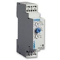
Manufacturer Part Number
88 865 503
Description
TIMER, CAGE CLAMP, MURC3
Manufacturer
Crouzet USA
Datasheet
1.88_826_503.pdf
(6 pages)
Specifications of 88 865 503
Contact Configuration
1CO
Nom Input Voltage
240VAC
Delay Time Range
0.1s To 100h
Relay Mounting
DIN Rail
Svhc
No SVHC (18-Jun-2010)
Adjustment Type
Screwdriver Slot
Coil Voltage Vac Nom
230V
Accuracy %
0.5%
Approval Bodies
UL & CSA


Function Ht :
Provides a cumulative time for contact opening.
On energisation, the output changes state,
remains in that state for the duration of timing
and resets at the end of the single cycle.
Function K:
On energisation, the output changes state.
On de-energisation timing commences and
the output only returns to the reset condition
after timing.
Function L :
Repetitive cycle comprising 2 independent
adjustable time bases. Each time base
corresponds alternately to a different output
state.
N.B. : The cycle starts with the output in the
rest position.
Function Li :
Repetitive cycle comprising 2 independent
adjustable time bases. Each time base
corresponds alternately to a different output
state.
N.B. : The cycle starts with the output in the
operating position.
Function N :
At the first control pulse the output is
energised.
To complete the timing the interval between
the two control pulses must be greater than
the timing set.
Function O :
On energisation, a first timing sequence
occurs and the output changes state.
With the closing of the control contact, the
output resets and the timing starts, with the
output being activated after timing.
For the timing to be completed, the interval
between the closing of two control contacts
must be greater than the timing set.
Delay on de-energisation - True delay OFF
2 relays timed or
1 relay timed and 1 instantaneous
Delay on energisation
2 relays timed or
1 relay timed and 1 instantaneous
with memory
Cyclic timing - Asymmetrical recycler
Cyclic timing - Asymmetrical recycler
2 relays timed or
1 relay timed and 1 instantaneous
2 relays timed or
1 relay timed and 1 instantaneous
"Safe-guard"
"Delayed safe-guard".
R1/R2
R1/R2
R2 Inst.
R1/R2
U
R
U
C
R
1 relay
U
R
U
1 relay
U
C
R
U
R1
R2
U
1 relay
U
C
R
1 relay
U
R
U
C
T1
T1
T1
T1
T
T2
T2
T2
T2
T
t1
t1
T = t1+t2
T = t1+t2
T
T
T
T
t2
t2
1/11
Function Pt :
Calculates the total opening time of a contact.
At the end of timing, the output is energised
for approximately 500 ms.
Function T :
After power-up, pressing or holding down the
switch closes the relay. Pressing the switch a
second time opens the relay.
Function Tt :
After power-up, pressing or holding down the
switch closes the relay and starts timing. The
relay opens at the end of timing or when the
switch is pressed a second time.
Function P :
Timing begins on energisation. At the end of
the timing period output relay R (or the load)
changes state for a period of approx. 500
milliseconds.
Function Q :
At the end of timing, the output is not
energised. It remains "open" (not
conducting) and will only change state
after the fixed time of Ti has elapsed.
Dwell time selectable
Function T :
energisation with memory
a - energisation by control signal
The timer sums the times for which the
control contact is closed (C1).
Reset is by the reset signal (C2) only.
b - energisation by supply voltage
The timer sums the times for which the
supply voltage (U) is on.
Reset is by the reset signal (C2) only
Function W :
After energisation, if the control contact
opens it causes output relay R (or the load)
to change state and timing to start. At the
end of the timing period, relay R resets to its
original state.
Timing on
Impulse relay
Impulse counter (delay on)
Timed impulse relay
Delayed fixed-length pulse
Star-delta"
Timing after pulse on control contact
U
R
U
R
U
C
R
U
C
R
U
C
R
U
C
R
t1
T= t1+t2
T
T
P = 500 ms
T
P
t2
T
Ti
P
t
1
Related parts for 88 865 503
Image
Part Number
Description
Manufacturer
Datasheet
Request
R

Part Number:
Description:
TIMER, MULTIFUNCTION
Manufacturer:
Crouzet USA
Datasheet:
Part Number:
Description:
Electromechanical Multifunction Timer
Manufacturer:
Crouzet USA
Datasheet:

Part Number:
Description:
Electromechanical Multifunction Timer
Manufacturer:
Crouzet USA
Datasheet:

Part Number:
Description:
MULTI-FUNCTION TIMER, DPDT, 100H, 230VAC
Manufacturer:
Crouzet USA
Datasheet:
Part Number:
Description:
TIMER, MULTIFUNCTION
Manufacturer:
Crouzet USA
Datasheet:
Part Number:
Description:
TIMER, FLIP/FLOP
Manufacturer:
Crouzet USA
Datasheet:

Part Number:
Description:
LAMP, INCAND, BAYONET, 6.8V, 12.98W
Manufacturer:
SPC TECHNOLOGY
Datasheet:

Part Number:
Description:
Circular MIL / Spec Connectors JT Series MIL-DTL-38999 II
Manufacturer:
Amphenol

Part Number:
Description:
M3 DISPLAY KIT, 12 I/O, 230VAC
Manufacturer:
Crouzet USA
Datasheet:
Part Number:
Description:
M3 DISPLAY KIT, 20 I/O, 24VDC
Manufacturer:
Crouzet USA
Datasheet:

Part Number:
Description:
Controller; CTD46 Dual Display Temperature, 1/16 DIN, NEMA 4X, 110/220VAC
Manufacturer:
Crouzet USA
Datasheet:

Part Number:
Description:
11R1084
Manufacturer:
Crouzet USA
Datasheet:
Part Number:
Description:
11R1086
Manufacturer:
Crouzet USA
Datasheet:
Part Number:
Description:
11R1087
Manufacturer:
Crouzet USA
Datasheet:
Part Number:
Description:
11R1089
Manufacturer:
Crouzet USA
Datasheet: