CSTCE8M00G52-B0 Murata, CSTCE8M00G52-B0 Datasheet - Page 5
CSTCE8M00G52-B0
Manufacturer Part Number
CSTCE8M00G52-B0
Description
Manufacturer
Murata
Datasheet
1.CSTCE8M00G52-B0.pdf
(14 pages)
Specifications of CSTCE8M00G52-B0
Lead Free Status / RoHS Status
Compliant


2
!Note
• This PDF catalog is downloaded from the website of Murata Manufacturing co., ltd. Therefore, it’s specifications are subject to change or our products in it may be discontinued without advance notice. Please check with our
• This PDF catalog has only typical specifications because there is no space for detailed specifications. Therefore, please approve our product specifications or transact the approval sheet for product specifications before ordering.
sales representatives or product engineers before ordering.
!Note
Chip type CERALOCK(R) with built-in load capacitors in
an extremely small package provides high accuracy.
MURATA's frequency adjustment and package technology
expertise has enabled the development of the chip
CERALOCK(R) with built-in load capacitors.
Chip CERALOCK(R) for automotive has achieved importance
in the worldwide automotive market. This diverse
series owes its development to MURATA's original mass
production techniques and high reliability.
1. The series has high reliability and is available
2. Oscillation circuits do not require external load
3. The series is available in a wide frequency range.
4. The resonators are extremely small and have a low
5. No adjustment is necessary for oscillation circuits.
1. Cluster panel and Control panel
2. Safety control
3. Engine ECU, Electronic Power Steering, Immobilizer,
4. Car Air-conditioner, Power Window, Remote Keyless
5. Electronic Toll Collection system, Car Navigation,
8
Ceramic Resonators (CERALOCKr)
MHz Chip Type -Standard Frequency Tolerance for Automotive-
Features
for wide temperature range.
capacitors.
profile.
Applications
(Anti-lock Brake System, Electronic Stability
Control, Airbag, etc.)
etc.
Entry system, etc.
etc.
14.00-20.00MHz
• Please read rating and !CAUTION (for storage, operating, rating, soldering, mounting and handling) in this catalog to prevent smoking and/or burning, etc.
• This catalog has only typical specifications because there is no space for detailed specifications. Therefore, please approve our product specifications or transact the approval sheet for product specifications before ordering.
CSTCE_V_C
0.4 0.1
0.5 (ref.)
0.4 0.1
0.1 0.1
(3)
1.2 0.1 1.2 0.1
3.0 max.
0.5 (ref.)
3.2 0.15
0.4 0.1
(2)
0.4 0.1
(1)
0.5 (ref.)
0.4 0.1
: EIAJ Monthly
Code
(in mm)
20.01-70.00MHz
8.00-13.99MHz
2.00-3.99MHz
4.00-7.99MHz
CSTCC_G_A
CSTCR_G_B
CSTCE_G_A
CSACV_X_Q
0.4 0.2
0.5 0.3
0.4 0.1
0.50 (ref.)
(0.5)
0.4 (ref.)
(Ref.)
1.1 0.1
(3)
1.85 0.3
0.45
0.75 0.1 1.5 0.1
1.6 0.2
0.3 0.3
1.2 0.2
0.2 0.2
0.8 0.1
(3)
3.7 0.2
0.5 0.2
0.5 0.3
M
0.4 0.1
(0.5)
(3)
(2)
2.5 0.1
0.1 0.1
(3)
1.6 0.2
0.4 (ref.)
(Ref.)
0.4 0.1
0.45
1.2 0.1 1.2 0.1
7.2 0.2
6.6 max.
1.4 0.2
(0.5)
0.4 0.2
0.5 0.3
Continued on the following page.
4.1 max.
3.2 0.15
(1)
3.0 max.
(2)
4.5 0.1
0.8 0.1
0.4 0.1 0.4 0.1
(2)
(2)
2.5 0.1
(Ref.)
0.4 (ref.)
0.45
0.4 0.1
1.5 0.1
0.50 (ref.)
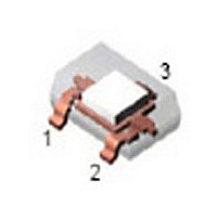
Terminals (1) and (3) are
interchangeable.
Terminal (2) should be soldered
only to fix the resonator onto P.C.B.
Terminal (2) should be electrically
floating so it cannot be connected
anywhere.
Thickness varies
with frequency.
*: EIAJ Monthly Code
1.2 0.2
(1)
0.8 0.1
(1)
(1)
1.3 0.1
0.50 (ref.)
0.4 0.1
t : 1.75 0.05
t : 1.55 0.05
(2.00—2.99MHz)
(3.00MHz—)
0.5 0.05
0.4 0.1
0.4 0.05
: EIAJ Monthly
Code
: EIAJ code
(in mm)
(in mm)
(in mm)
(in mm)
P16E.pdf
09.5.20
Related parts for CSTCE8M00G52-B0
Image
Part Number
Description
Manufacturer
Datasheet
Request
R

Part Number:
Description:
Murata Microblower 20x20 DCDC Driver Board - Samples Only
Manufacturer:
Murata
Part Number:
Description:
357-036-542-201 CARDEDGE 36POS DL .156 BLK LOPRO
Manufacturer:
Murata
Datasheet:
Part Number:
Description:
Manufacturer:
Murata
Datasheet:
Part Number:
Description:
Manufacturer:
Murata
Datasheet:
Part Number:
Description:
Manufacturer:
Murata
Datasheet:
Part Number:
Description:
Manufacturer:
Murata
Datasheet:
Part Number:
Description:
Manufacturer:
Murata
Datasheet:
Part Number:
Description:
Manufacturer:
Murata
Datasheet:
Part Number:
Description:
Manufacturer:
Murata
Datasheet:
Part Number:
Description:
BLM21BD751SN1On-Board Type (DC) EMI Suppression Filters
Manufacturer:
Murata
Datasheet:
Part Number:
Description:
BLM15AG100SN1On-Board Type (DC) EMI Suppression Filters
Manufacturer:
Murata
Datasheet:
Part Number:
Description:
NFE31PT222Z1E9On-Board Type (DC) EMI Suppression Filters
Manufacturer:
Murata
Datasheet:
Part Number:
Description:
Chip Coil
Manufacturer:
Murata
Datasheet:
Part Number:
Description:
Chip Coil
Manufacturer:
Murata
Datasheet: