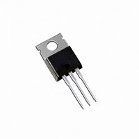
IRF9530NPBF International Rectifier, IRF9530NPBF Datasheet
Home Discrete Semiconductor Products MOSFETs, GaNFETs - Single IRF9530NPBF
Manufacturer Part Number
IRF9530NPBF
Description
MOSFET P-CH 100V 14A TO-220AB
Manufacturer
International Rectifier
Specifications of IRF9530NPBF
Fet Type
MOSFET P-Channel, Metal Oxide
Fet Feature
Standard
Rds On (max) @ Id, Vgs
200 mOhm @ 8.4A, 10V
Drain To Source Voltage (vdss)
100V
Current - Continuous Drain (id) @ 25° C
14A
Vgs(th) (max) @ Id
4V @ 250µA
Gate Charge (qg) @ Vgs
58nC @ 10V
Input Capacitance (ciss) @ Vds
760pF @ 25V
Power - Max
79W
Mounting Type
Through Hole
Package / Case
TO-220-3 (Straight Leads)
Channel Type
P
Current, Drain
-14 A
Gate Charge, Total
58 nC
Package Type
TO-220AB
Polarization
P-Channel
Power Dissipation
79 W
Resistance, Drain To Source On
0.2 Ohm
Temperature, Operating, Maximum
+175 °C
Temperature, Operating, Minimum
-55 °C
Time, Turn-off Delay
45 ns
Time, Turn-on Delay
15 ns
Transconductance, Forward
3.2 S
Voltage, Breakdown, Drain To Source
-100 V
Voltage, Drain To Source
–100 V
Voltage, Forward, Diode
-1.6 V
Voltage, Gate To Source
±20 V
Transistor Polarity
P-Channel
Drain-source Breakdown Voltage
- 100 V
Gate-source Breakdown Voltage
20 V
Continuous Drain Current
- 14 A
Mounting Style
Through Hole
Gate Charge Qg
38.7 nC
Lead Free Status / RoHS Status
Lead free / RoHS Compliant
Available stocks
l
l
l
l
l
l
l
θ
θ
θ
ƒ
‚
G
S
D
TO-220AB
®
DS(on)
DSS
D
Ω
Related parts for IRF9530NPBF
IRF9530NPBF Summary of contents
G ‚ ƒ ® D DSS Ω DS(on TO-220AB ...
‚ Ω J Ω ƒ ≤ ≤ ≤ „ ≤ „ „ Ω Ω, „ „ „ ≤ ≤ ...
VGS TOP - 15V - 10V - 8.0V - 7.0V - 6.0V - 5.5V - 5.0V BOTTOM - 4.5V 10 -4.5V 1 20µs PULSE WIDTH T = 25°C c 0.1 0 Drain-to-Source Voltage (V) DS ...
1MHz iss rss oss ds gd 1600 1200 C iss 800 C oss C rss ...
T , Case Temperature ( 0.50 1 0.20 0.10 0.05 0.1 0.02 SINGLE PULSE 0.01 (THERMAL RESPONSE) 0.01 0.00001 0.0001 t d(on) ...
D.U DRIVER -20V 0.01 Ω (BR)DSS Charge 700 600 500 400 300 15V 200 100 ...
Driver Gate Drive Period P.W. D.U.T. I Waveform SD Reverse Recovery Body Diode Forward Current Current D.U.T. V Waveform DS Diode Recovery Re-Applied Voltage Body Diode Inductor Curent Ripple ≤ ...
Dimensions are shown in millimeters (inches) 10.54 (.415) 10.29 (.405) 2.87 (.113) 2.62 (.103) 15.24 (.600) 14.84 (.584) 14.09 (.555) 13.47 (.530) 1.40 (.055) 3X 1.15 (.045) 2.54 (.100) 2X NOTES: 1 DIMENSIONING & TOLERANCING PER ANSI Y14.5M, 1982. 2 ...
Note: For the most current drawings please refer to the IR website at: http://www.irf.com/package/ ...
Related keywords
irf9540 irf9530 irf9520 irf9510 irf9530n irf9540nspbf irf9530strlpbf irf9530pbf IRF9530NPBF datasheet IRF9530NPBF data sheet IRF9530NPBF pdf datasheet IRF9530NPBF component IRF9530NPBF part IRF9530NPBF distributor IRF9530NPBF RoHS IRF9530NPBF datasheet download


