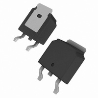
IRFRC20TRRPBF Vishay, IRFRC20TRRPBF Datasheet - Page 5

IRFRC20TRRPBF
Manufacturer Part Number
IRFRC20TRRPBF
Description
MOSFET N-CH 600V 2A DPAK
Manufacturer
Vishay
Datasheet
1.IRFRC20TR.pdf
(8 pages)
Specifications of IRFRC20TRRPBF
Fet Type
MOSFET N-Channel, Metal Oxide
Fet Feature
Standard
Rds On (max) @ Id, Vgs
4.4 Ohm @ 1.2A, 10V
Drain To Source Voltage (vdss)
600V
Current - Continuous Drain (id) @ 25° C
2A
Vgs(th) (max) @ Id
4V @ 250µA
Gate Charge (qg) @ Vgs
18nC @ 10V
Input Capacitance (ciss) @ Vds
350pF @ 25V
Power - Max
2.5W
Mounting Type
Surface Mount
Package / Case
DPak, TO-252 (2 leads+tab), SC-63
Transistor Polarity
N Channel
Continuous Drain Current Id
2A
Drain Source Voltage Vds
600V
On Resistance Rds(on)
4.4ohm
Rds(on) Test Voltage Vgs
10V
Leaded Process Compatible
Yes
Peak Reflow Compatible (260 C)
Yes
Rohs Compliant
Yes
Configuration
Single
Resistance Drain-source Rds (on)
4.4 Ohms
Drain-source Breakdown Voltage
600 V
Gate-source Breakdown Voltage
+/- 20 V
Continuous Drain Current
2 A
Power Dissipation
2.5 W
Maximum Operating Temperature
+ 150 C
Mounting Style
SMD/SMT
Fall Time
25 ns
Minimum Operating Temperature
- 55 C
Rise Time
23 ns
Lead Free Status / RoHS Status
Lead free / RoHS Compliant
Lead Free Status / RoHS Status
Lead free / RoHS Compliant, Lead free / RoHS Compliant
Document Number: 91285
S10-1139-Rev. D, 17-May-10
Fig. 9 - Maximum Drain Current vs. Case Temperature
Fig. 11 - Maximum Effective Transient Thermal Impedance, Junction-to-Case
IRFRC20, IRFUC20, SiHFRC20, SiHFUC20
90 %
10 %
Fig. 10a - Switching Time Test Circuit
Fig. 10b - Switching Time Waveforms
V
V
DS
GS
R
Pulse width ≤ 1 µs
Duty factor ≤ 0.1 %
g
10 V
V
GS
t
d(on)
V
DS
t
r
D.U.T.
Vishay Siliconix
R
D
t
d(off)
t
f
+
-
www.vishay.com
V
DD
5


