IRFPS40N50LPBF Vishay, IRFPS40N50LPBF Datasheet
IRFPS40N50LPBF
Specifications of IRFPS40N50LPBF
Available stocks


Related parts for IRFPS40N50LPBF

IRFPS40N50LPBF Summary of contents
Page 1
... Pulsed Source Current SM Ã (Body Diode) V Diode Forward Voltage SD t Reverse Recovery Time rr Q Reverse Recovery Charge rr I Reverse Recovery Current RRM t Forward Turn-On Time on Document Number: 91260 IRFPS40N50LPbF SMPS MOSFET HEXFET V R DSS 500V Max. @ 10V 10V 29 GS 180 540 4.3 ± - 150 300 (1 ...
Page 2
... IRFPS40N50LPbF Static @ T = 25°C (unless otherwise specified) J Symbol Parameter V Drain-to-Source Breakdown Voltage (BR)DSS ∆V /∆T Breakdown Voltage Temp. Coefficient (BR)DSS J R Static Drain-to-Source On-Resistance DS(on) V Gate Threshold Voltage GS(th) I Drain-to-Source Leakage Current DSS I Gate-to-Source Forward Leakage GSS Gate-to-Source Reverse Leakage R Internal Gate Resistance ...
Page 3
... Fig 1. Typical Output Characteristics 1000 100 ° 150 ° 20µs PULSE WIDTH 0 Gate-to-Source Voltage (V) GS Fig 3. Typical Transfer Characteristics Document Number: 91260 IRFPS40N50LPbF 1000 TOP 100 BOTTOM 10 4.5V 1 ° 0.1 0.1 10 100 Fig 2. Typical Output Characteristics 3 2.5 2.0 1.5 1.0 0.5 = 50V 0.0 -60 -40 -20 ...
Page 4
... IRFPS40N50LPbF 1000000 0V MHZ C iss = SHORTED C rss = C gd 100000 C oss = 10000 Ciss 1000 Coss 100 Crss Drain-to-Source Voltage (V) Fig 5. Typical Capacitance vs. Drain-to-Source Voltage 47A 100 200 Q , Total Gate Charge (nC) G Fig 7. Typical Gate Charge vs. Gate-to-Source Voltage Document Number: 91260 100 1000 0 1000 ...
Page 5
... SINGLE PULSE (THERMAL RESPONSE) 0.001 0.00001 0.0001 Fig 11. Maximum Effective Transient Thermal Impedance, Junction-to-Case Document Number: 91260 IRFPS40N50LPbF Fig 10a. Switching Time Test Circuit V DS 90% 125 150 ° 10 d(on) Fig 10b. Switching Time Waveforms Notes: 1 ...
Page 6
... IRFPS40N50LPbF 1000 OPERATION IN THIS AREA LIMITED BY R DS(on) 100 ° ° 150 C J Single Pulse 1 10 100 V , Drain-to-Source Voltage (V) DS Fig 12. Maximum Safe Operating Area D.U 20V 0.01 Ω Fig 14a. Unclamped Inductive Test Circuit Current Regulator Same Type as D.U.T. 50KΩ ...
Page 7
... Driver Gate Drive P.W. D.U.T. I Waveform SD Reverse Recovery Current D.U.T. V Waveform DS Re-Applied Voltage Inductor Curent * Fig 16. For N-Channel HEXFET Document Number: 91260 IRFPS40N50LPbF + • • ƒ • - „ • • • • P.W. Period D = Period Body Diode Forward Current ...
Page 8
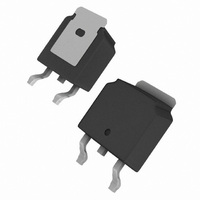
... IRFPS40N50LPbF Case Outline and Dimensions — Super-247 Super-247 (TO-274AA) Part Marking Information EXAMPLE: THIS IS AN IRFPS37N50A WITH ASSEMBLY LOT CODE 1789 ASSEMBLED ON WW 19, 1997 IN THE ASSEMBLY LINE "C" INTERNATIONAL RECTIFIER LOGO ASSEMBLY LOT CODE Note: "P" in assembly line position indicates "Lead-Free" ...
Page 9
... Except as provided in Vishay's terms and conditions of sale for such products, Vishay assumes no liability whatsoever, and disclaims any express or implied warranty, relating to sale and/or use of Vishay products including liability or warranties relating to fitness for a particular purpose, merchantability, or infringement of any patent, copyright, or other intellectual property right. ...