SI4420DY International Rectifier, SI4420DY Datasheet
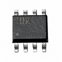
MOSFET N-CH 30V 12.5A 8-SOIC

SI4420DY

Manufacturer Part Number
SI4420DY
Description
MOSFET N-CH 30V 12.5A 8-SOIC
Manufacturer
International Rectifier
Series
HEXFET®r
Datasheet

Specifications of SI4420DY

Fet Type
MOSFET N-Channel, Metal Oxide
Fet Feature
Logic Level Gate
Rds On (max) @ Id, Vgs
9 mOhm @ 12.5A, 10V
Drain To Source Voltage (vdss)
30V
Current - Continuous Drain (id) @ 25° C
12.5A
Vgs(th) (max) @ Id
1V @ 250µA
Gate Charge (qg) @ Vgs
78nC @ 10V
Input Capacitance (ciss) @ Vds
2240pF @ 15V
Power - Max
2.5W
Mounting Type
Surface Mount
Package / Case
8-SOIC (3.9mm Width)
Lead Free Status / RoHS Status
Contains lead / RoHS non-compliant
Other names
*SI4420DY

Available stocks

Company
Part Number
Manufacturer
Quantity
Price
Part Number:
SI4420DY
Manufacturer:
ST
Quantity:
16 000
Part Number:
SI4420DY
Manufacturer:
ICS
Quantity:
10
Part Number:
SI4420DY
Manufacturer:
VISHAY/威世
Quantity:
20 000
Part Number:
SI4420DY-E3
Manufacturer:
VISHAY
Quantity:
1 902
Part Number:
SI4420DY-T1
Manufacturer:
Vishay
Quantity:
2 512
Part Number:
SI4420DY-T1
Manufacturer:
VISHAY
Quantity:
1 000
Part Number:
SI4420DY-T1
Manufacturer:
VISHAY/威世
Quantity:
20 000
Part Number:
SI4420DY-T1-E3
Manufacturer:
PULSE
Quantity:
10
Part Number:
SI4420DY-T1-E3
Manufacturer:
VISHAY/威世
Quantity:
20 000
Part Number:
SI4420DY-T1-GE3
Manufacturer:
VISHAY/威世
Quantity:
20 000
Part Number:
SI4420DY-TI
Manufacturer:
SILICONIX
Quantity:
20 000
Part Number:
SI4420DYT1
Manufacturer:
NEC
Quantity:
2 625
Part Number:
SI4420DYTRPBF
Manufacturer:
International Rectifier
Quantity:
25 338
Description
Absolute Maximum Ratings
Thermal Resistance
This N-channel HEXFET
using International Rectifier's advanced HEXFET power
MOSFET technology. The low on-resistance and low gate
charge inherent to this technology make this device ideal
for low voltage or battery driven power conversion
applications
The SO-8 package with copper leadframe offers enhanced
thermal characteristics that allow power dissipation of
greater that 800mW in typical board mount applications.
www.irf.com
V
I
I
I
P
P
E
V
T
R
D
D
DM
J,
DS
D
D
AS
GS
@ T
@ T
JA
N-Channel MOSFET
Low On-Resistance
Low Gate Charge
Surface Mount
Logic Level Drive
@T
@T
T
STG
A
A
A
A
= 25°C
= 70°C
= 25°C
= 70°C
Drain- Source Voltage
Continuous Drain Current, V
Pulsed Drain Current
Power Dissipation
Power Dissipation
Linear Derating Factor
Single Pulse Avalanche Energy
Gate-to-Source Voltage
Junction and Storage Temperature Range
Maximum Junction-to-Ambient
®
power MOSFET is produced
Parameter
Parameter
GS
GS
@ 10V
@ 10V
G
S
S
S
1
2
3
4
T o p V ie w
HEXFET
8
7
6
5
-55 to + 150
Max.
Max.
±12.5
0.02
±10
±50
400
± 20
50
D
D
D
D
2.5
1.6
A
30
A
SO-8
Si4420DY
®
R
Power MOSFET
DS(on)
V
DSS
= 0.009
PD - 93835
= 30V
Units
Units
W/°C
°C/W
W
mJ
°C
V
A
V
1
1/3/2000

Related parts for SI4420DY

SI4420DY Summary of contents

Page 1

... Junction and Storage Temperature Range J, STG Thermal Resistance Parameter R Maximum Junction-to-Ambient JA www.irf.com HEXFET Max. @ 10V ±12 10V GS 0.02 - 150 Max 93835 Si4420DY ® Power MOSFET 30V DSS 0.009 D DS(on) SO-8 Units 30 V ±10 A ±50 2.5 W 1.6 W/°C 400 mJ ± °C Units 50 ° ...

Page 2

... Si4420DY Electrical Characteristics @ T Parameter V Drain-to-Source Breakdown Voltage (BR)DSS Breakdown Voltage Temp. Coefficient (BR)DSS J R Static Drain-to-Source On-Resistance DS(on) V Gate Threshold Voltage GS(th) g Forward Transconductance fs I Drain-to-Source Leakage Current DSS Gate-to-Source Forward Leakage I GSS Gate-to-Source Reverse Leakage Q Total Gate Charge g Q Gate-to-Source Charge ...

Page 3

... TOP BOTTOM 100 ° 10 0.1 10 100 Fig 2. Typical Output Characteristics 2 1.5 1.0 0.5 8.0 9.0 0.0 -60 -40 -20 Fig 4. Normalized On-Resistance Si4420DY VGS 15V 10V 8.0V 7.0V 6.0V 5.5V 5.0V 4.5V 4.5V 20µs PULSE WIDTH ° 150 Drain-to-Source Voltage (V) DS 12.5A ...

Page 4

... Si4420DY 4000 1MHz iss rss oss ds gd 3000 C iss 2000 C oss 1000 C rss Drain-to-Source Voltage (V) DS Fig 5. Typical Capacitance Vs. Drain-to-Source Voltage 1000 ° 100 10 1 0.0 1.0 2.0 3.0 V ,Source-to-Drain Voltage (V) SD Fig 7. Typical Source-Drain Diode Forward Voltage SHORTED ds 16 ...

Page 5

... SINGLE PULSE (THERMAL RESPONSE) 0.1 0.01 0.0001 0.001 Fig 11. Typical Effective Transient Thermal Impedance, Junction-to-Ambient www.irf.com 100 125 150 0.01 ° Fig 10. Typical Power Vs. Time 1. Duty factor Peak 0.01 0 Rectangular Pulse Duration (sec) 1 Si4420DY 0 (sec ) Notes thJA 100 5 A 100 ...

Page 6

... Si4420DY 10V 4. rain C urren Fig 12. Typical On-Resistance Vs. Drain Current 3.0 2.5 2.0 1.5 1.0 -60 - Temperature (°C) Fig 14. Typical Threshold Voltage Vs.Temperature 6 0.012 0.010 0.008 0.006 A 4 Fig 13. Typical On-Resistance Vs. Gate 1000 800 250µA 600 400 200 0 100 140 180 25 Starting T , Junction Temperature ( C) Fig 15 ...

Page 7

... SO-8 Package Outline SO-8 Part Marking Information www.irf.com Si4420DY 7 ...

Page 8

... Si4420DY SO-8 Tape & Reel Information Dimensions are shown in millimeters (inches . . ( & LIN -48 1 & -54 1. WORLD HEADQUARTERS: 233 Kansas St., El Segundo, California 90245, Tel: (310) 252-7105 IR GREAT BRITAIN: Hurst Green, Oxted, Surrey RH8 9BB, UK Tel 1883 732020 IR GERMANY: Saalburgstrasse 157, 61350 Bad Homburg Tel 6172 96590 IR JAPAN: K& ...

Related keywords