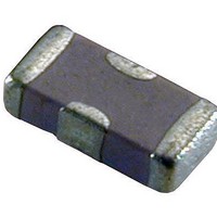
V3F418A400Y3GDP AVX Corporation, V3F418A400Y3GDP Datasheet - Page 8

V3F418A400Y3GDP
Manufacturer Part Number
V3F418A400Y3GDP
Description
Varistors 18 VDC 42v 150pF .1 J
Manufacturer
AVX Corporation
Series
V2Fr
Datasheet
1.V3F418A400Y3GDP.pdf
(8 pages)
Specifications of V3F418A400Y3GDP
Technology
Multilayer Array
Capacitance Value
150pF
Clamping Current
1A
Clamping Voltage
42V
Ac Voltage Rating (max)
13VAC
Dc Voltage Rating (max)
18VDC
Mounting
Surface Mount
Surge Current (max)
20A
Size Code
0612
Lead Spacing
0.76mm
Product Length (mm)
1.6mm
Product Depth (mm)
3.25mm
Product Height (mm)
1.22mm
Energy
0.1Joule
Varistor Voltage
25.5V
Product
MLV
Voltage Rating Dc
18 V
Voltage Rating Ac
13 V
Peak Surge Current
20 A
Surge Energy Rating
0.1 J
Capacitance
150 pF
Dimensions
1.25 mm W x 2.01 mm L x 1.143 mm H
Package / Case
0805 (2012 mm)
Lead Free Status / RoHS Status
Compliant
TransFeed
AVX Multilayer Ceramic Transient Voltage Suppressors
TVS Protection and EMI Attenuation in a Single Chip
PERFORMANCE CHARACTERISTICS
SPECIFICATION COMPARISON
A comparison table showing typical element parameters and resulting
performance features for MLV and MLVF is shown above.
54
APPLICATIONS
FEATURES
Sensor/Keyboard/
Touchscreen Input
Sensor Input
Keyboard
5ph
<600nh
<0.025Ω
100pf to 2.5nf
see VI curves
>0.25 x 10
<250ps
• EMI Suppression
• Broadband I/O Filtering
• Vcc Line Conditioning
• Small Size
• Low ESR
• Ultra-fast Response Time
• Broad S21 Characteristics
MLVF
0805
12
Ω
L s
L p
R on
C
R v
R p
Typical turn on time
Typical frequency response
ANALOG
DIGITAL
DIGITAL
BOARD
BOARD
BOARD
Fig. 1 – System Interface
PARAMETER
typical
typical
typical
typical
typical
typical
By X Bus
MARKET SEGMENTS
• Computers
• Automotive
• Power Supplies
• Multimedia Add-On Cards
• Bar Code Scanners
• Remote Terminals
• Medical Instrumentation
• Test Equipment
• Transceivers
• Cellular Phones / Pagers
RF BOARD
ANALOG
N/A
<1.5nh
<0.1Ω
100pf to 5.5nf
see VI curves
>1 x 10
<500ps
DIGITAL
BOARD
BOARD
0805
MLV
12
Ω
Display
Fig. 3 – Power Conversion Circuits/Power Switching Circuits
POWER
MAIN
INPUT
TYPICAL CIRCUITS REQUIRING
TRANSIENT VOLTAGE
PROTECTION AND EMI FILTERING
The following applications and schematic diagrams
show where TransFeed TVS/ EMI filtering devices might
be used:
• System Board Level Interfaces: (Fig. 1)
• Voltage Regulation (Fig. 2)
• Power Conversion Circuits (Fig. 3)
• GaAs FET Protection (Fig. 4)
+3.3V
+5V
+12V
Digital to RF
Analog to Digital
Digital to Analog
Fig. 4 – GaAs FET Protection
Fig. 2 – Voltage Regulators
MANAGEMENT
REGULATOR
POWER
CHIP
ASIC
+3.3V
+1.8V
+
OUTPUT
INTERFACE
CARD


