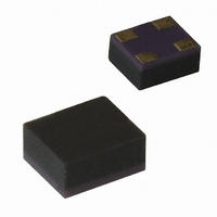
HMPP-3860-TR1 Avago Technologies US Inc., HMPP-3860-TR1 Datasheet - Page 5

HMPP-3860-TR1
Manufacturer Part Number
HMPP-3860-TR1
Description
DIODE PIN GP 50V 1A MINIPAK
Manufacturer
Avago Technologies US Inc.
Datasheet
1.HMPP-3865-BLK.pdf
(10 pages)
Specifications of HMPP-3860-TR1
Diode Type
PIN - Single
Voltage - Peak Reverse (max)
50V
Current - Max
1A
Capacitance @ Vr, F
0.2pF @ 50V, 1MHz
Resistance @ If, F
22 Ohm @ 1mA, 100MHz
Package / Case
4-MiniPak (1412)
Capacitance Cd Max @ Vr F
0.2pF
Resistance @ If
22ohm
Forward Current If(av)
50mA
No. Of Pins
4
Series Resistance @ If
1.5ohm
Peak Reflow Compatible (260 C)
No
Capacitance Ct
0.2pF
Breakdown Voltage
50V
Rohs Compliant
Yes
Forward Current If
1A
Lead Free Status / RoHS Status
Contains lead / RoHS non-compliant
Power Dissipation (max)
-
Lead Free Status / RoHS Status
Lead free / RoHS Compliant, Contains lead / RoHS non-compliant
Available stocks
Company
Part Number
Manufacturer
Quantity
Price
Part Number:
HMPP-3860-TR1
Manufacturer:
AVAGO/安华高
Quantity:
20 000
Diode Lifetime and Resistance
The resistance of a PIN diode is controlled by the con-
ductivity (or resistivity) of the I layer. This conductivity is
controlled by the density of the cloud of carriers (charges)
in the I layer (which is, in turn, controlled by the DC bias).
Minority carrier lifetime, indicated by the Greek symbol
τ, is a measure of the time it takes for the charge stored
in the I layer to decay, when forward bias is replaced with
reverse bias, to some predetermined value. This lifetime
can be short (35 to 200 nsec. for epitaxial diodes) or it
can be relatively long (400 to 3000 nsec. for bulk diodes).
Lifetime has a strong influence over a number of PIN
diode parameters, among which are distortion and basic
diode behavior.
To study the effect of lifetime on diode behavior, we first
define a cutoff frequency f
this cutoff frequency can be as high as 30 MHz while for
our longer lifetime diodes f
which are ten times f
act like a current controlled variable resistor. At frequen-
cies which are one tenth (or less) of f
like an ordinary PN junction diode. Finally, at 0.1f
10f
to mention that in this frequency range, the diode can
exhibit very strong capacitive or inductive reactance — it
will not behave at all like a resistor.
The HMPP-386x family features a typical lifetime of 300 to
500 ns, so 10f
5 MHz, the resistance of this diode will follow the curve
given in Figure 2. From this curve, it can be seen that the
HMPP-386x family produces a lower resistance at a given
value of bias current than most attenuator PIN diodes,
making it ideal for applications where current consump-
tion is important.
5
C
, the behavior of the diode is very complex. Suffice it
C
for this part is 5 MHz. At any frequency over
C
(or more), a PIN diode does indeed
C
= 1/τ. For short lifetime diodes,
C
≅ 400 KHz. At frequencies
C
, a PIN diode acts
C
≤ f ≤
Dielectric Relaxation Frequency and Diode Capacitance
f
given by the equation
f
where…
ρ = bulk resistivity of the I-layer
ε = ε
In the case of an epitaxial diode with a value for ρ of 10Ω-
cm, f
very pure material, ρ can be as high as 2000, resulting in
a value of f
The implications of a low f
uator and switch circuits. At operating frequencies below
f
junction capacitance. At operating frequencies well above
f
For the HMPP-386x family, f
in very low capacitance at zero bias for frequencies above
1 GHz. See Figure 1.
DR
DR
DR
DR
= bulk susceptance of silicon
, reverse bias (as much as 50V) is needed to minimize
, the curve of capacitance vs. reverse bias is flat.
=
(Dielectric Relaxation Frequency) for a PIN diode is
0
DR
2πρε
ε
R
1
will be in Ku-Band. For a bulk diode fabricated on
= 10
DR
-12
of 80 MHz.
F/cm
DR
DR
are very important in RF atten-
is around 500 MHz, resulting


