ATF-551M4-TR1 Avago Technologies US Inc., ATF-551M4-TR1 Datasheet - Page 5
ATF-551M4-TR1
Manufacturer Part Number
ATF-551M4-TR1
Description
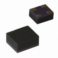
IC TRANS E-PHEMT GAAS MINIPAK
Manufacturer
Avago Technologies US Inc.
Datasheet
1.ATF-551M4-TR2.pdf
(23 pages)
Specifications of ATF-551M4-TR1
Gain
17.5dB
Mfg Application Notes
ATF-541M4 AppNote
Transistor Type
pHEMT FET
Frequency
2GHz
Voltage - Rated
5V
Current Rating
100mA
Noise Figure
0.5dB
Current - Test
10mA
Voltage - Test
2.7V
Power - Output
14.6dBm
Package / Case
4-MiniPak (1412)
Power Dissipation Pd
270mW
Rf Transistor Case
MiniPak
Frequency Max
10GHz
Noise Figure Typ
0.5dB
Frequency Min
450MHz
Continuous Drain Current Id
0.1µA
Drain Current Idss Max
10mA
Drain Source Voltage Vds
2.7V
Rohs Compliant
Yes
Lead Free Status / RoHS Status
Lead free / RoHS Compliant
Other names
516-1509-2
Available stocks
Company
Part Number
Manufacturer
Quantity
Price
Company:

Part Number:
ATF-551M4-TR1
Manufacturer:
AVAGO
Quantity:
120 000
Part Number:
ATF-551M4-TR1
Manufacturer:
AVAGO/安华高
Quantity:
20 000
Company:
Part Number:
ATF-551M4-TR1G
Manufacturer:
AVAGO
Quantity:
140 000


ATF-551M4 Typical Performance Curves, continued
Notes:
1. Measurements at 2 GHz with biasing 2.7V, 10 mA were made on a fixed tuned production test board that was tuned for optimal OIP3 match
2. The Fmin values are based on a set of 16 noise figure measurements made at 16 different impedances using an ATN NP5 test system. From
5
Figure 11. Gain vs. I
Figure 14. IIP3 vs. I
with reasonable noise figure. This circuit represents a trade-off between optimal noise match, maximum OIP3 match and a realizable match
based on production test board requirements. Measurements taken other than 2.7V, 10 mA biasing was made using a double stub tuner at
the input tuned for low noise and a double stub tuner at the output tuned for maximum OIP3. Circuit losses have been de-embedded from
actual measurements.
these measurements Fmin is calculated. Refer to the noise parameter measurement section for more information.
20
19
18
17
16
15
18
16
14
12
10
8
6
4
2
0
0
0
5
5
10
10
I
I
15
15
ds
ds
ds
ds
(mA)
(mA)
and V
and V
20
20
ds
ds
25
25
at 2 GHz
at 2 GHz
30
30
2V
2.7V
3V
2V
2.7V
3V
[1]
[1]
.
35
35
.
Figure 12. Fmin vs. I
Figure 15. P1dB vs. I
17
16
15
14
13
12
11
10
0.6
0.5
0.4
0.3
0.2
0.1
0
0
0
5
5
10
10
I
I
15
15
ds
ds
ds
ds
(mA)
(mA)
and V
and V
20
20
ds
ds
25
25
at 2 GHz
at 2 GHz
2V
2.7V
3V
30
2V
2.7V
3V
30
[2]
[1]
35
35
.
.
Figure 13. OIP3 vs. I
36
32
28
24
20
16
0
5
10
I
15
ds
ds
(mA)
and V
20
ds
25
at 2 GHz
30
2V
2.7V
3V
[1]
35
.
Related parts for ATF-551M4-TR1
Image
Part Number
Description
Manufacturer
Datasheet
Request
R

Part Number:
Description:
IC TRANS E-PHEMT 2GHZ SOT-343
Manufacturer:
Avago Technologies US Inc.
Datasheet:

Part Number:
Description:
IC PHEMT 2GHZ 3V 30MA SOT-343
Manufacturer:
Avago Technologies US Inc.
Datasheet:

Part Number:
Description:
IC PHEMT 2GHZ 2.7V 10MA MINIPAK
Manufacturer:
Avago Technologies US Inc.
Datasheet:

Part Number:
Description:
IC PHEMT 2GHZ 2.7V 10MA SOT-343
Manufacturer:
Avago Technologies US Inc.
Datasheet:
Part Number:
Description:
IC PHEMT 2GHZ 3V 60MA SOT-343
Manufacturer:
Avago Technologies US Inc.
Datasheet:
Part Number:
Description:
IC PHEMT 1.9GHZ 80MA LN SOT-343
Manufacturer:
Avago Technologies US Inc.
Datasheet:
Part Number:
Description:
IC PHEMT 1.9GHZ 15MA LN SOT-343
Manufacturer:
Avago Technologies US Inc.
Part Number:
Description:
IC PHEMT 1.9GHZ 15MA LN SOT-343
Manufacturer:
Avago Technologies US Inc.
Datasheet:
Part Number:
Description:
IC PHEMT 1.9GHZ 60MA LN SOT-343
Manufacturer:
Avago Technologies US Inc.
Datasheet:
Part Number:
Description:
IC TRANS E-PHEMT 2GHZ SOT-343
Manufacturer:
Avago Technologies US Inc.
Datasheet:
Part Number:
Description:
IC TRANS E-PHEMT 2GHZ SOT-343
Manufacturer:
Avago Technologies US Inc.
Datasheet:
Part Number:
Description:
IC TRANS E-PHEMT 2GHZ SOT-343
Manufacturer:
Avago Technologies US Inc.
Datasheet:

Part Number:
Description:
TRANSISTOR,HEMT,N-CHAN,5.5V V(BR)DSS,175mA I(DSS),SOT-343R
Manufacturer:
Avago Technologies US Inc.
Part Number:
Description:
TRANSISTOR,HEMT,N-CHAN,3V V(BR)DSS,15mA I(DSS),SOT-363
Manufacturer:
Avago Technologies US Inc.
Datasheet:
Part Number:
Description:
TRANSISTOR,HEMT,N-CHAN,4.5V V(BR)DSS,90mA I(DSS),SOT-343R
Manufacturer:
Avago Technologies US Inc.
Datasheet: