NSS12200WT1G ON Semiconductor, NSS12200WT1G Datasheet

TRANSISTOR PNP 2A 12V SC-88

NSS12200WT1G

Manufacturer Part Number
NSS12200WT1G
Description
TRANSISTOR PNP 2A 12V SC-88
Manufacturer
ON Semiconductor
Datasheet

Specifications of NSS12200WT1G

Transistor Type
PNP
Current - Collector (ic) (max)
2A
Voltage - Collector Emitter Breakdown (max)
12V
Vce Saturation (max) @ Ib, Ic
290mV @ 20mA, 1A
Current - Collector Cutoff (max)
100nA
Dc Current Gain (hfe) (min) @ Ic, Vce
100 @ 800mA, 1.5 V
Power - Max
450mW
Frequency - Transition
100MHz
Mounting Type
Surface Mount
Package / Case
SC-70-6, SC-88, SOT-363
Lead Free Status / RoHS Status
Lead free / RoHS Compliant
Other names
NSS12200WT1G

Available stocks

Company
Part Number
Manufacturer
Quantity
Price
Part Number:
NSS12200WT1G
Manufacturer:
ON Semiconductor
Quantity:
900
Part Number:
NSS12200WT1G
Manufacturer:
ON
Quantity:
30 000
NSS12200WT1G
12 V, 3 A, Low V
PNP Transistor
transistors are miniature surface mount devices featuring ultra low
saturation voltage (V
are designed for use in low voltage, high speed switching applications
where affordable efficient energy control is important.
in portable and battery powered products such as cellular and cordless
phones, PDAs, computers, printers, digital cameras and MP3 players.
Other applications are low voltage motor controls in mass storage
products such as disc drives and tape drives. In the automotive
industry they can be used in air bag deployment and in the instrument
cluster. The high current gain allows e
driven directly from PMU’s control outputs, and the Linear Gain
(Beta) makes them ideal components in analog amplifiers.
Features
Benefits
Stresses exceeding Maximum Ratings may damage the device. Maximum
Ratings are stress ratings only. Functional operation above the Recommended
Operating Conditions is not implied. Extended exposure to stresses above the
Recommended Operating Conditions may affect device reliability.
MAXIMUM RATINGS
© Semiconductor Components Industries, LLC, 2009
October, 2009 − Rev. 1
Collector-Emitter Voltage
Collector-Base Voltage
Emitter-Base Voltage
Collector Current − Continuous
Collector Current
Electrostatic Discharge
ON Semiconductor’s e
Typical application are DC−DC converters and power management
Compliant
High Specific Current and Power Capability Reduces Required PCB Area
High Current Capability (3 A)
High Power Handling (Up to 650 mW)
Low V
Small Size
These Devices are Pb−Free, Halogen Free/BFR Free and are RoHS
Reduced Parasitic Losses Increases Battery Life
CE(s)
Rating
(170 mV Typical @ 1 A)
− Peak
CE(sat)
(T
A
= 25°C)
) and high current gain capability. These
2
PowerEdge family of low V
Symbol
V
V
V
ESD
I
CEO
CBO
EBO
I
CM
C
CE(sat)
2
PowerEdge devices to be
Max
−5.0
−2.0
−3.0
−12
−12
HBM Class 3
MM Class C
1
CE(sat)
Unit
Vdc
Vdc
Vdc
Adc
NSS12200WT1G
†For information on tape and reel specifications,
PNP LOW V
including part orientation and tape sizes, please
refer to our Tape and Reel Packaging Specifications
Brochure, BRD8011/D.
EQUIVALENT R
Device
ORDERING INFORMATION
BASE
V2 = Specific Device Code
M = Date Code
G = Pb−Free Package
DEVICE MARKING
http://onsemi.com
3
SC−88/SOT−363
12 VOLTS
6
1
3.0 AMPS
CE(sat)
CASE 419B
STYLE 20
COLLECTOR
(Pb−Free)
Package
SOT−363
EMITTER
1, 2, 5, 6
V2
Publication Order Number:
G
1
M
DS(on)
4
TRANSISTOR
Tape & Reel
NSS12200W/D
163 mW
Shipping
3000 /

Related parts for NSS12200WT1G

NSS12200WT1G Summary of contents

Page 1

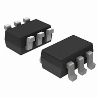
... V2 = Specific Device Code M = Date Code G = Pb−Free Package ORDERING INFORMATION Device Package Shipping NSS12200WT1G SOT−363 3000 / (Pb−Free) Tape & Reel †For information on tape and reel specifications, including part orientation and tape sizes, please refer to our Tape and Reel Packaging Specifications Brochure, BRD8011/D ...

Page 2

THERMAL CHARACTERISTICS Characteristic Total Device Dissipation T = 25°C A Derate above 25°C Thermal Resistance, Junction−to−Ambient Total Device Dissipation T = 25°C A Derate above 25°C Thermal Resistance, Junction−to−Ambient Thermal Resistance, Junction−to−Lead 6 Total Device Dissipation (Single Pulse < 10 ...

Page 3

A 800 mA 0 100 mA 500 BASE CURRENT (mA) B Figure 1. Collector Emitter Voltage vs. Base Current 400 125°C 300 25°C 200 100 T ...

Page 4

0. 0.01 0.01 SINGLE PULSE 0.001 0.00001 0.0001 0.001 0.01 0 TIME (s) Figure 7. Normalized Thermal Response http://onsemi.com 4 ...

Page 5

... Pb−Free strategy and soldering details, please download the ON Semiconductor Soldering and Mounting Techniques Reference Manual, SOLDERRM/D. ON Semiconductor and are registered trademarks of Semiconductor Components Industries, LLC (SCILLC). SCILLC reserves the right to make changes without further notice to any products herein ...

Related keywords