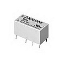
9-1393792-0 TE Connectivity, 9-1393792-0 Datasheet - Page 220

9-1393792-0
Manufacturer Part Number
9-1393792-0
Description
Electromechanical Relay DPDT 3A 24VDC 3.872KOhm Through Hole
Manufacturer
TE Connectivity
Type
Signal Relayr
Specifications of 9-1393792-0
Contact Arrangement
DPDT
Dc Coil Voltage
24 V
Coil Current
6.2 mA
Mounting
Through Hole
Relay Construction
Non-Latching
Coil Voltage Dc
24V
Contact Form
2 Form C
Voltage Rating (vdc)
220V
Voltage Rating (vac)
250V
Dropout Volt (min)
1.2VDCV
Coil Resistance
3.872kohm
Pick-up Voltage (max)
19.2VDC
Maximum Power Rating
60W/125VA
Operate Time
5ms
Contact Current Rating
3A
Contact Material
AgNi/Au
Coil Suppression Diode
No
Push To Test Button
No
Led Indicator
No
Seal
Unsealed
Product Height (mm)
11mm
Product Depth (mm)
10mm
Product Length (mm)
20.2mm
Operating Temp Range
-25C to 85C
Pin Count
8
Mounting Style
Through Hole
Termination Style
PC Pin
Package / Case
DIP
Lead Free Status / Rohs Status
Compliant
- Current page: 220 of 484
- Download datasheet (15Mb)
512
Ordering Information
Stock Items – We recommend that our authorized distributors stock the following items for immediate delivery.
T92P7A22-24
T92P7A22-120
Outline Dimensions
Mounting & Termination Type 1
(14.86 ± .13)
Mounting & Termination Type 5
(16.00 ± .13)
.585 ± .005
.630 ± .005
.913 MAX.
Dimensions are shown for
reference purposes only.
1. Basic Series:
2. Enclosure:
3. Contact Arrangement:
4. Coil Input:
5. Mounting & Termination:
6. Contact Material:
7. Coil Voltage: (See Coil Data Table)
‡ New option. Consult factory for detailed ratings, specifications and availability.
(23.19)
1.21 MAX.
(30.73)
T92 = Printed circuit board / panel mount power relay.
P = Plastic dust cover (unsealed).
7 = 2 form A (DPST-NO).
A = AC voltage, 60 Hz. or 50/60 Hz. (See Coil Data Table)
1 = Printed circuit board mount; printed circuit board terminals.
2 = Panel mount via flanged cover; .250” (6.35mm) x .032” (.81mm) quick connect terminals.
3 = Panel mount via flanged cover; .187” (4.75mm) x .032” (.81mm) quick connect terminals for coil and .250” (6.35mm) for contacts.
4 = Panel mount via flanged cover, .187” (4.75mm) x .020” (.51mm) quick connect terminals for coil and .250” (6.35mm) for contacts.
5 = Panel mount via flanged cover, M4 screw terminals w/ captive pressure plates. Requires Enclosure P and Contact Arrangement 7.‡
2 = Silver cadmium oxide.
(DC)
(60Hz.)
(50/60Hz.)
T92P7A22-240
T92P7D12-12
2.700 MAX.
(59.71
2.135 MAX.
12 = 12VDC
12 = 12VAC
110 = 100/110VAC
2.35
(68.58)
2.06 MAX.
(54.23)
1.618 ± .020
(41.10 ± .51)
(52.32)
.309 ± .005
(7.85 ± .13)
.005
.13)
T92P7D12-24
T92P7D22-12
.032 TYP.
2.010 MAX.
(0.81)
(51.05)
(3.96)
1.000 ± .010
(25.40 ± .25)
.156
.090 (2.29)
#8 SCREW
RAD. FOR
S = Immersion cleanable, tape sealed plastic case (code 1).
11 = 2 form C (DPDT).
24 = 24VDC
24 = 24VAC
120 = 110/120VAC
Dimensions are in inches over
(millimeters) unless otherwise
specified.
Top sealed, not immersion cleanable, not tape sealed
on bottom (codes 2, 3 & 4).
1.36 MAX.
(34.54)
1.431 MAX.
T92P7D22-24
T92P11A22-24
.047 TYP.
1.36 MAX.
(36.34)
Typical Part Number
(34.54)
(1.19)
.250 TYP.
(6.35)
240 = 220/240VAC
48 = 48VDC
T92P11A22-120
T92P11A22-240
D = DC voltage.
Catalog 1308242
Issued 3-03
B
Suggested PC Board Layout
(Bottom View)
Note: An alternate PC board layout utilizes .076
Mounting & Termination Types 2, 3 & 4
.203 TYP.
(14.86 ± .13)
.585 ± .005
(16.00)
T92
(5.16)
(9.27)
.630 TYP.
.365
.630
T92P11D22-12
T92P11D22-24
1.04 MAX.
(16.00)
(4.12)
.162
(26.42)
(7.85)
.003 (1.93
same center-to-center spacing shown
above. Use of the rectangular holes is
recommended for improved solderability.
.309
Specifications and availability
subject to change.
110 = 110VDC
277 = 250/277VAC
S
(14.86)
(59.71 ± .13)
.585
2.35 ± .005
.076) diameter holes on the
T92S7D12-12
T92S7D12-24
(41.10)
1.618
2.700 MAX.
2.05 MAX.
.052 TYP.
(41.10 ± .51)
(68.58)
(52.07)
11
.309 ± .005
(7.85 ± .13)
1.618 TYP.
(1.32)
D
T92S11D22-12
T92S11D22-24
(4.70)
.185
.072 TYP.
(1.83)
(25.40)
1.495 MAX.
1.000
(37.97)
FOR #8 SCREW
2
.090 RAD.
Wiring Diagram
Only necessary terminals are
present on single throw models.
(2.29)
2
6
4
8
www.tycoelectronics.com
Technical support:
Refer to inside back cover.
1.36 MAX.
3
7
(34.54)
2
0
1
-24
P&B
Related parts for 9-1393792-0
Image
Part Number
Description
Manufacturer
Datasheet
Request
R

Part Number:
Description:
CRIMP, RECEPTACLE
Manufacturer:
TE Connectivity
Datasheet:

Part Number:
Description:
PIGGYBACK DISCONNECT, 6.35MM, CRIMP BLUE
Manufacturer:
TE Connectivity
Datasheet:

Part Number:
Description:
Manufacturer:
TE Connectivity
Datasheet:

Part Number:
Description:
CRIMP TERMINAL, FEMALE, BLUE
Manufacturer:
TE Connectivity
Datasheet:

Part Number:
Description:
Manufacturer:
TE Connectivity
Datasheet:

Part Number:
Description:
CONN HEADR BRKWAY .100 13POS R/A
Manufacturer:
Tyco Electronics
Datasheet:

Part Number:
Description:
CONN HEADR BRKWAY .100 13POS R/A
Manufacturer:
Tyco Electronics
Datasheet:

Part Number:
Description:
CONN HDR BRKWAY .100 13POS VERT
Manufacturer:
Tyco Electronics
Datasheet:

Part Number:
Description:
CONN HDR BRKWAY .100 13POS VERT
Manufacturer:
Tyco Electronics
Datasheet:

Part Number:
Description:
CONN HDR BRKWAY .100 13POS VERT
Manufacturer:
Tyco Electronics
Datasheet:

Part Number:
Description:
CONN HEADR BRKWAY .100 13POS R/A
Manufacturer:
Tyco Electronics
Datasheet:

Part Number:
Description:
CONN HEADR BRKWAY .100 13POS STR
Manufacturer:
Tyco Electronics
Datasheet:

Part Number:
Description:
CONN HEADR BRKWAY .100 13POS STR
Manufacturer:
Tyco Electronics
Datasheet:

Part Number:
Description:
CONN HEADR BRKWAY .100 13POS STR
Manufacturer:
Tyco Electronics
Datasheet:

Part Number:
Description:
CONN HEADR BRKWAY .100 13POS R/A
Manufacturer:
Tyco Electronics
Datasheet:


