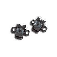
HEDS-9711#R50 Avago Technologies US Inc., HEDS-9711#R50 Datasheet - Page 3

HEDS-9711#R50
Manufacturer Part Number
HEDS-9711#R50
Description
Encoders 2 Channel 200CPR
Manufacturer
Avago Technologies US Inc.
Type
Optical Encoderr
Datasheet
1.HEDS-9711R50.pdf
(8 pages)
Specifications of HEDS-9711#R50
Number Of Channels
2
Mounting Style
PCB
Supply Voltage
5 V
Product
Optical
Technology
Linear
Termination Style
Solder Pin
Pulses Per Revolution
900
Detents
No
Motion
Rotary
Index Output
Not Indexed
Encoder Signal
Digital Square Wave
Built In Switch
No
Shaft Style
Hollow
Shaft Diameter (mm)
2mm
Operating Supply Voltage (typ)
5VDC
Operating Temperature Min Deg. C
15C
Operating Temperature Max Deg. C
45C
Terminal Type
PC Pins
Lead Free Status / RoHS Status
Lead free / RoHS Compliant
Available stocks
Company
Part Number
Manufacturer
Quantity
Price
3
Waveform Definition
Electrical Characteristics
Electrical Characteristics over Recommended Operating Range, Typical at 25 C.
Name
Analog Peak
Analog Peak-to-Peak
Analog Offset
State Width
State Width Error
Pulse Width
Pulse Width Error
Parameter
Supply Current
Paramenter
Ipp
Ioffset
State Width
State Width Error
Pulse Width
Pulse Width Error The deviation, in electrical degrees, of each pulse width
ANALOG
DIGITAL
A
B
A
B
Symbol
I
CC
Ibm
S1
The peak-to-peak signal magnitude in A of the
The offset in A from the mid-point of the analog
Min.
Definition
The absolute value in A of the magnitude of the
analog signal (i.e., one-sided reading).
analog signal.
peak-to-peak signal to the zero current point.
The number of electrical degrees between a transition
in channel A and the neighboring transition in channel B.
There are four states per cycle, each nominally 90 e.
The transitions are determined by where the analog
signal crosses the Zero point.
The deviation, in electrical degrees, of each state width
from its ideal value of 90 e.
The number of electrical degrees that an analog output
is greater than zero during one cycle. This value is
nominally 180 e or 1/2 cycle.
from its ideal value of 180 e.
P
Iap
S2
Typ.
17
P
Ibp
S3
Iam
Max.
40
S4
Units
mA
Label
Iap, Ibp,
Iam, Ibm
Iapp
Ibpp
State 1
State 2
State 3
State 4
P
Notes


