746610-1 TE Connectivity, 746610-1 Datasheet - Page 2
746610-1
Manufacturer Part Number
746610-1
Description
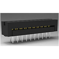
Conn IDC Connector M 10 POS 2.54mm IDT RA Cable Mount
Manufacturer
TE Connectivity
Type
IDC Connectorr
Series
AMP-LATCHr
Specifications of 746610-1
Pitch
2.54 mm
Number Of Rows
2
Number Of Contacts
10
Gender
M
Contact Plating
Bright Tin-Lead Over Nickel
Termination Method
IDT
Connector Type
Wire To Board
Contact Termination
IDC / IDT
No. Of Contacts
10
No. Of Rows
2
Pitch Spacing
2.54mm
Rohs Compliant
No
Product Line
AMP-LATCH
Termination Method To Pc Board
Through Hole - Solder
Pcb Mounting Orientation
Vertical
Pcb Mount Retention
Without
Pcb Mount Alignment
Without
Termination Method To Wire/cable
IDC
Ul File Number
E28476
Csa File Number
LR 7189
Contact - Rated Current (a)
1
Operating Voltage Reference
AC
Operating Voltage (vac)
250
Wire/cable Size (awg)
26 – 30
Wire/cable Size (mm²)
0.051 – 0.15
Wire/cable Size (cma)
101 – 296
Tail Length (mm [in])
3.96 [0.156]
Tail Orientation
In-line
Profile Height (y-axis) (mm [in])
6.43 [0.253]
Number Of Positions
10
Centerline (mm [in])
2.54 [0.100]
Row-to-row Spacing (mm [in])
2.54 [0.100]
Length (x-axis) (mm [in])
17.27 [0.6799]
Width (z-axis) (mm [in])
7.06 [0.278]
Contact Type
Pin
Contact Base Material
Phosphor Bronze
Contact Plating, Mating Area, Material
Gold or Palladium Nickel or Performance Based
Contact Plating, Mating Area, Thickness (µm [?in])
2.54 [100]
Tail Plating Material
Tin-Lead
Tail Plating, Thickness (µm [?in])
2.54 [100]
Connector Style
Plug
Housing Color
Black
Ul Flammability Rating
UL 94V-0
Rohs/elv Compliance
Not ELV/RoHS compliant
Lead Free Solder Processes
Wave solder capable to 240°C, Wave solder capable to 260°C, Wave solder capable to 265°C
Agency/standard
UL, CSA
Ul Rating
Recognized
Ul Voltage Rating (vac)
250
Operating Temperature (°c [°f])
-65 – +105 [-85 – +221]
Applies To
Printed Circuit Board
Accepts Wire Insulation Diameter, Range (mm [in])
0.81 – 1.07 [0.032 – 0.042]
Pcb Thickness, Recommended (mm [in])
3.18 [0.125]
Application Use
Wire-to-Board
Contact Transmits (typical Application)
Signal (Data)
Packaging Method
Tube


3.3.
3.4.
3.5.
Rev A
Exam ination of product.
Term ination resistance.
Insulation resistance.
Dielectric withstanding voltage.
Solderability.
Vibration, random .
Physical shock.
Therm al shock.
Ratings
!
!
Perform ance and Test Description
Product is designed to m eet the electrical, m echanical and environm ental perform ance requirem ents
specified in Figure 1. Unless otherwise specified, all tests shall be perform ed at am bient environm ental
conditions per Test Specification 109-1.
Test Requirem ents and Procedures Sum m ary
Test Description
Current: 1 am pere m axim um per contact
Tem perature: -65 to 105 C
Meets requirem ents of product
drawing and Application
Specification 114-40005.
15 m illiohm s m axim um initial.
5000 m egohm s m inim um .
500 vac at sea level.
Contact tabs shall have m inim um
of 95% solder coverage.
No discontinuities of 1 m icrosecond
or longer duration.
See Note.
No discontinuities of 1 m icrosecond
or longer duration.
See Note.
See Note.
Figure 1 (continued)
ENVIRONMENTAL
MECHANICAL
ELECTRICAL
Requirem ent
Visual, dim ensional and functional
per applicable quality inspection
plan.
TE 109-6-1.
Subject sam ples to 50 m v
m axim um open circuit at 100 m a
m axim um .
See Figure 3.
TE Spec 109-28-4.
Test between adjacent contacts of
sam ples.
TE Spec 109-29-1.
Test between adjacent contacts of
sam ples.
TE Spec 109-11-1.
Subject contacts to solderability.
TE Spec 109-21-7.
Subject m ated sam ples to 4.41 G's
rm s between 5 to 500 Hz. 15
m inutes in each of 3 m utually
perpendicular planes.
TE Spec 109-26-1.
Subject m ated sam ples to 50 G's
half-sine shock pulses of 11
m illiseconds duration. 3 shocks in
each direction applied along 3
m utually perpendicular planes, 18
total shocks.
TE Spec 109-22.
Subject sam ples to 5 cycles
between -65 and 105 C.
Procedure
108-40013
2 of 4
Related parts for 746610-1
Image
Part Number
Description
Manufacturer
Datasheet
Request
R

Part Number:
Description:
Conn IDC Connector M 14 POS 2.54mm IDT RA Cable Mount
Manufacturer:
TE Connectivity
Datasheet:
Part Number:
Description:
Conn IDC Connector M 26 POS 2.54mm IDT RA Cable Mount
Manufacturer:
TE Connectivity
Datasheet:
Part Number:
Description:
Conn IDC Connector M 34 POS 2.54mm IDT RA Cable Mount
Manufacturer:
TE Connectivity
Datasheet:
Part Number:
Description:
Conn IDC Connector M 16 POS 2.54mm IDT RA Cable Mount
Manufacturer:
TE Connectivity
Datasheet:
Part Number:
Description:
Conn IDC Connector M 20 POS 2.54mm IDT RA Cable Mount
Manufacturer:
TE Connectivity
Datasheet:

Part Number:
Description:
High Speed / Modular Connectors 30P HEADER ASSY
Manufacturer:
TE Connectivity
Datasheet:

Part Number:
Description:
High Speed / Modular Connectors REC 6X005P R/A LT B-PLANE HS3
Manufacturer:
TE Connectivity
Datasheet:

Part Number:
Description:
High Speed / Modular Connectors 2MM HM RCPT 50P R/A AU
Manufacturer:
TE Connectivity
Datasheet:

Part Number:
Description:
High Speed / Modular Connectors 2MM HM RCPT 50P R/A AU
Manufacturer:
TE Connectivity
Datasheet:


Part Number:
Description:
Manufacturer:
TE Connectivity
Datasheet:


Part Number:
Description:
Manufacturer:
TE Connectivity
Datasheet:

Part Number:
Description:
Manufacturer:
TE Connectivity
Datasheet:

Part Number:
Description:
Manufacturer:
TE Connectivity
Datasheet: