104549-6 TE Connectivity, 104549-6 Datasheet
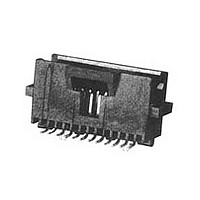
Conn Shrouded Header HDR 40 POS 1.27mm Solder ST SMD Tube

104549-6

Manufacturer Part Number
104549-6
Description
Conn Shrouded Header HDR 40 POS 1.27mm Solder ST SMD Tube
Manufacturer
TE Connectivity
Type
Shrouded Headerr
Series
AMPMODU System 50r
Datasheets

Specifications of 104549-6

Pitch
1.27 mm
Number Of Rows
2
Number Of Contacts
40
Gender
HDR
Contact Plating
Gold Over Nickel
Termination Method
Solder
Connector Type
Wire To Board
Contact Termination
Surface Mount Vertical
No. Of Contacts
40
No. Of Rows
2
Pitch Spacing
1.27mm
Rohs Compliant
No
Shrouded
Yes
Mount Angle
Vertical
Pcb Mount Style
Surface Mount
Pcb Mount Retention
With
Hold-down Post Material
Copper Alloy
Hold-down Post Plating
Tin-Lead over Nickel
Voltage (vac)
30
Insulation Resistance (m?)
5,000
Dielectric Withstanding Voltage (v)
500
Termination Post Length (mm [in])
2.54 [0.100]
Solder Tail Contact Plating
Tin-Lead
Number Of Positions
40
Pcb Mount Retention Type
Hold Down Post(s)
Contact Base Material
Phosphor Bronze
Contact Plating, Mating Area, Material
Gold (30)
Connector Style
Plug
Housing Material
Thermoplastic - GF
Ul Flammability Rating
UL 94V-0
Housing Color
Black
Rohs/elv Compliance
ELV compliant, 5 of 6 Compliant
Lead Free Solder Processes
Reflow solder capable to 245°C, Reflow solder capable to 260°C
Approved Standards
UL E28476, CSA LR7189
Temperature Range (°c)
-65 – +105
Packaging Method
Tube
1.
1.1.
1.2.
2.
2.1.
3.
3.1.
3.2.
©2011 Tyco Electronics Corporation,
a TE Connectivity Ltd. Company
All Rights Reserved
TE logo is a trademark.
SCOPE
Content
This specification covers performance, tests and quality requirements for AMPMODU* System 50
interconnection system including through hole and surface mount connectors. This miniature board-to-
board system consists of receptacles and .015 inch square post headers on .050 by .100 inch centerline
interface spacing; .050 inch between circuits within a row and .100 inch between rows. Surface mount
headers and receptacles are designed to be soldered to the surface of printed wiring boards having
pads with pre-applied solder paste. Conventional processes shall be used in placing and reflowing
solder paste as defined in applicable documents. This specification applies when receptacles and/or
headers are mounted to G-10 or FR-4 epoxy printed wiring boards.*
Qualification
When tests are performed on subject product line, procedures specified in 109 Series Test
Specifications shall be used. All inspections shall be performed using applicable inspection plan and
product drawing.
APPLICABLE DOCUMENTS
The following documents form a part of this specification to the extent specified herein. Unless
otherwise specified, latest edition of the document applies. In the event of conflict between
requirements of this specification and product drawing, product drawing shall take precedence. In the
event of conflict between requirements of this specification and referenced documents, this specification
shall take precedence.
TE Connectivity (TE) Documents
!
!
!
!
!
REQUIREMENTS
Design and Construction
Product shall be of design, construction and physical dimensions specified on applicable product
drawing.
Materials
!
!
!
109-1: General Requirements for Test Specifications
109 Series: Test Specifications as indicated in Figure 1
114-25031: Application Specification
114-25035: Application Specification
501-287: Qualification Test Report
Contact:
Holddowns: Copper alloy, tin-lead plating
Housing: Black thermoplastic, UL94V-0
Header: Phosphor bronze, gold plating on mating area, tin-lead plating on tails
Receptacle: Phosphor bronze, gold plating on mating area, tin-lead plating on tails
| Indicates change
*Trademark
Product
Specification
Interconnection System. AMPMODU* System 50
For latest revision, visit our website at www.te.com/documents.
For Regional Customer Service, visit our website at www.te.com
Other products, logos, and company names might be trademarks of their respective owners.
108-1093
11Mar11 Rev B
1 of 8
LOC B

Related parts for 104549-6

104549-6 Summary of contents

Page 1

... Holddowns: Copper alloy, tin-lead plating ! Housing: Black thermoplastic, UL94V-0 ©2011 Tyco Electronics Corporation, | Indicates change a TE Connectivity Ltd. Company *Trademark All Rights Reserved TE logo is a trademark. For latest revision, visit our website at www.te.com/documents. For Regional Customer Service, visit our website at www.te.com Other products, logos, and company names might be trademarks of their respective owners ...

Page 2

Ratings ! Voltage: 30 volts AC ! Current: See Figures 4A and 4B for applicable current carrying capability ! Temperature: -65 to 105° C 3.4. Performance and Test Description Product is designed to meet electrical, mechanical and environmental performance ...

Page 3

Test Description Durability. Contact retention. Mating force. Unmating force. Thermal shock. Humidity-temperature cycling. Temperature life. Mixed flowing gas. Shall meet visual requirements, show no physical damage and shall meet requirements of NOTE additional tests as specified in Test Sequence in ...

Page 4

Product Qualification and Requalification Test Sequence Test or Examination Examination of product Termination resistance Insulation resistance Dielectric withstanding voltage Temperature rise vs current Vibration Physical shock Durability Contact retention Mating force Unmating force Thermal shock Humidity-temperature cycling Temperature life ...

Page 5

QUALITY ASSURANCE PROVISIONS 4.1. Qualification Testing A. Sample Selection Samples shall be prepared in accordance with applicable Instruction Sheets and shall be selected at random from current production. All test groups shall consist of the longest position size of ...

Page 6

Rev B Figure 3 Termination Resistance Measurement Points 108-1093 ...

Page 7

To determine acceptable current carrying capacity for percentage connector loading, use NOTE Multiplication Factor (F) from above chart and multiply it times Base rated Current for a single circuit at maximum ambient operating temperature as shown in Figure 4A. Rev ...

Page 8

Note: See AMP Drawing 30-468787 Rev B Figure 5 Vibration & Physical Shock Mounting Fixture 108-1093 ...

Related keywords