5-104656-2 TE Connectivity, 5-104656-2 Datasheet
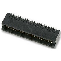
5-104656-2
Specifications of 5-104656-2
Available stocks


Related parts for 5-104656-2


5-104656-2 Summary of contents
Page 1
Ribbon Cable Interconnect Solutions ...
Page 2
... Grid Grid Pages 10 and 11 Page 15 System 50 Ultra ATA Bus Receptacles Compliant Receptacles Pages 8-11 Pages 13-15 Mates to .50" x .50" Mates to .050" x .050" Micro-MaTch Micro-MaTch Female Top Entry, Female Side Entry, 215079 Series, 215460 Series, PCB Connector PCB Connector Page 34 Page 35 Male-on-Wire ...
Page 3
... Mates to .100" x .100" 2-Row Universal or Low-Profile Headers Pages 75-96 622 and 636 AMP-LATCH Novo Series Female Connectors Socket Connectors Pages 48-51 Pages 52 and 53 .050" [1.27 mm] Cable Pitch (Continued) Mates to 2-Row DIP Sockets or Solders to PCB .100" x .300" .100" x .600" Footprint Footprint ...
Page 4
I I RoHS I Customer I Support Center I ...
Page 5
...
Page 6
...
Page 7
...
Page 8
...
Page 9
...
Page 10
...
Page 11
...
Page 12
...
Page 13
...
Page 14
...
Page 15
...
Page 16
...
Page 17
...
Page 18
... MPMODU 50/50 Grid Connector System 1 ...
Page 19
... Board-to-Board Vertical Receptacles and Headers .250±.006 .320±.006 .390±.006 19 ...
Page 20
... Board-to-Board Vertical Receptacles, Double Row, .050 x .050 [1.27 x 1.27] Centerline Note .120 .050 .050 .266 .516 .766 1.016 1.266 1.516 1.766 2.016 2.516 .028 .050 .187 ...
Page 21
... Board-to-Board Vertical Headers, Double Row, .050 x .050 [1.27 x 1.27] Centerline .050 .2255 .2975 .3675 .372 .622 .872 1.122 1.372 1.622 1.872 2.122 2.372 2.622 Note: .225 .050 A .030 A .030 A .030 .050 .050 .050 21 ...
Page 22
... .820 .950 1.070 1.200 1.320 1.450 1.570 1.700 1.820 1.950 2.070 2.200 2.320 2.450 2.570 .162 .010 .047 .061 .110 .060 .200 .322 .450 .572 .700 .822 .950 1.072 1.200 1.322 1.450 1.572 1.700 1.822 1.950 2.072 2.200 2.322 2.450 2.572 ...
Page 23
Board-to-Board Right- ngle Headers ...
Page 24
... Board-to-Board Right- ngle Headers, Double Row, .050 x .050 [1.27 x 1.27] Centerline Note: 24 ...
Page 25
... Cable-to-Board Connectors ...
Page 26
... Cable-to-Board Receptacle Connectors, Double Row, .050 x .050 [1.27 x 1.27] Centerline Note: 26 ...
Page 27
Terminating Covers for Cable Connectors Note: 27 ...
Page 28
Tooling for Cable Connectors Note: 2 ...
Page 29
Performance Specifications Note: 29 ...
Page 30
Micro-MaTch Miniature Connector System ...
Page 31
Micro-MaTch Miniature Connector System Overview Technical Data 31 ...
Page 32
... Female Top Entry Part Number 215079 4 Female Side Entry Part Number 215460 8 SMD Top Entry Part Number 188275 Image 32 COSI Part Number 338095 Male-on-Board Part Number 338096 Part Number 215464 Part Number 338097 Description (see also page 33) Paddle Board Part Number 215570 ...
Page 33
... Male Connectors Male-on-Wire Part Number 215083 Female Connectors Female Top Entry C Part Number 215079 Female Side Entry C Part Number 215460 SMD Top Entry D Part Number 188275 Image A (max) B (max) Part Number 338095 Male-on-Board Part Number 338096 Part Number 215464 Part Number 338097 ...
Page 34
... A B Max. 2.54 [.100] 1.27 [.050] 0.80 [.031] 2.54 [.100] Typical Hole Pattern Not Solder Side Shown Dimensions (mm 2500 Connectors/Reel METRIC imensions are millimeters over inches 1.5 5.1 Max. 4.0 [.200] [.157] 1.9 3.1 [.074] [.122] 1.40 1.80 [.055] [.071] 1 ...
Page 35
... A 2.54 [0.09] 1.27 [0.05] 2.54 (N-1)x1.27 [0.09] Recommended PCB Hole Layout Not Solder Side Shown Dimensions (mm 2500 Connectors/Reel METRIC imensions are millimeters over inches 5.8 [0.23] 5.3 Max. [0.21] 0.80 Nom. [0.03] Part Numbers 250 Connectors/Box 35 ...
Page 36
... A=(N-1)*1.27 0.5B-2.5 5.0 [.197 2.54 [.100] 1.50 [.059] 1.50 [.059] Recommended PCB Layout Top View Dimensions (mm 2500 Connectors/Reel METRIC imensions are millimeters over inches 5.0 [.197] 7.0 [.276] 5.0 [.197] 3.00 Minimum [.118] Solder Path Length Part Numbers 250 Connectors/Box ...
Page 37
... Section A-A 2.54 [.100] Dimensions (mm) No. of Positions A B METRIC imensions are millimeters over inches 5.00 [.197] A 6.75 [.266] 7.10 [.280] 0.80 [.031] 1.27 [.050] 2.54 [.100] Typical Hole Pattern Not Solder Side Shown Part Numbers 2500 Connectors/Reel 250 Connectors/Box 37 ...
Page 38
... Micro-MaTch Miniature Connector System — Male-on-Wire Connector No. of Positions Max. B Max. 5.10 C Max. [.201] Section A-A Dimensions (mm) Part Numbers 2500 Connectors/Reel METRIC imensions are millimeters over inches A 10.20 [.402] 250 Connectors/Box ...
Page 39
... Section A-A 2.54 [.100] Dimensions (mm) No. of Positions METRIC imensions are millimeters over inches 5.00 [.197] A 6.75 [.266] 7.10 [.280] 0.80 [.031] 1.27 [.050] 2.54 [.100] Typical Hole Pattern Not Solder Side Shown Part Numbers 2500 Connectors/Reel 250 Connectors/Box 39 ...
Page 40
... C 2.54 [.100] 1.27 [.050] 2.65 [.104] B Max. A Max. 9.10 Max. [.358] 12.40 Max. [.488] 0.25 Cut Off [.010] Max. 8.65 Max. [.341] Part Number Large reel, 15.000 Small reel, 750 Part Numbers 2500 Connectors/Reel 250 Connectors/Box ...
Page 41
Micro-MaTch Miniature Connector System — Specials 41 ...
Page 42
Micro-MaTch Miniature Connector System pplication Tooling 42 ...
Page 43
Micro-MaTch Miniature Connector System pplication Tooling 43 ...
Page 44
Micro-MaTch Miniature Connector System Lead ssembly Micro-MaTch Miniature Connector System Sample Box 44 ...
Page 45
... ...
Page 46
...
Page 47
imensions are millimeters over inches 47 ...
Page 48
...
Page 49
49 ...
Page 50
... 50 ...
Page 51
... 51 ...
Page 52
... imensions are millimeters over inches ...
Page 53
... 53 ...
Page 54
... imensions are millime- ters over inches ...
Page 55
... 55 ...
Page 56
... A .319 Before [8.1] Crimping .100 .100 [2.54] B [2.54] .100 [2.54] .008 x .024 [0.2 x 0.6] ...
Page 57
... 57 ...
Page 58
... 58 ...
Page 59
... 59 ...
Page 60
60 ...
Page 61
61 ...
Page 62
... Pitch [.053] [.049] [.055] [.110] Optional Mounting Boss 0.50 C [.020] 0.70 Min. [.028] 3.40 [.134] Ø 0.80 [.031] 1.35 [.053] A 1.40 2.80 3.00 [.118] 3.40 [.134] 4.20 [.165] 0.05 0.80 [.002] [.031] 1.30 [.051] 0.70 Min. [.028] 0.50 [.020] ...
Page 63
... Thermoplastic, black Universal I/O Pin Connectors — pages 45 and 46 .335 H C Note: .108 ±.002 F Note: G .134 (packaged, 50 per bag) (packaged, 1000 per box) he snap-in polarizer .134 provides military polarization. .680 1.806 .880 1.749 .980 1.721 1.180 1.664 1.380 1.607 1 ...
Page 64
... Thermoplastic, see table for color Note: 64 .500 .245 [12.70] [6.22] .185 [4.70] .029 [0.58] ...
Page 65
... Thermoplastic, see table for color Note: Key Plug (Plugs into Contact) Alternate Configuration Keying Plug Part No. 104072-1 (10 Keying Plugs per Comb) 65 ...
Page 66
... Natural color PVC, 94-VTM-1 rating (thin material) — pages 52-55 — pages 13-15 — pages 16 and 17 — pages 48-51 Note: 66 Note: .44 .64 .74 .88 1.08 1.18 1.38 1.58 1.82 2.32 2.80 ...
Page 67
... Glass-filled polyester, black Universal I/O Pin Connectors — page 45 Glass-filled polyester, blue Female Socket Connectors — page 54 and 55 .240 A [6.10] .565 [14.35] .240 A [6.10] .570 [14.46] .313 ±.004 C A .098 ±.002 B .472 .672 .872 .972 1.172 1.372 1 ...
Page 68
... Glass-filled polyester, black .106 MP-L TCH Novo Connectors — pages 48-51 Ultra T Compliant Bus Connectors — pages 13-15 Glass-filled polyester, black 2 mm Receptacle Connectors — pages 16 and 17 .276 [7.01] Typ. .056 [1.42] Note .186 .581 .015 .130 Rad. Typ. [0.38] [3 ...
Page 69
... Glass-filled PBT, see table for color Female Socket Connectors — pages 52 and 53 Note: A .236 [6.00] .555 [14.10] .477 .677 .877 .977 1.177 1.377 1.477 1.677 1.877 2.177 2.677 3.177 3.377 69 ...
Page 70
Need more information? ...
Page 71
...
Page 72
ı ıı 72 ıı ...
Page 73
... Min. 1.25 Min [40 Min.] [30 Min 610] center-to-center center-to-center 2. [70 to 205] end-to-end 2. [ 220] end-to-end 1.50 Min. [35 Min.] center-to-center 1.74 to 105 [ 665] end-to-end 1.74 to 105 [ 665] end-to-end 1.74 to 105 [ 665] end-to-end 1.60 to 100 [ 540] center-to-end 1.60 to 100 [ 540] center-to-center 3 Min. [75 Min.] center-to-center 73 ...
Page 74
7 ...
Page 75
... ...
Page 76
... Dia. Typ. Recommended PC Board Hole Layout For Manual Insertion Dimensions A B .800 [20.32] .400 [10.16] 1.000 [25.40] .600 [15.24] 1.100 [27.94] .700 [17.78] 1.300 [33.02] .900 [22.86] 1.500 [38.10] 1.100 [27.94] 1.600 [40.64] 1.200 [30.48] 2.000 [50.80] 1.600 [40.64] 2 ...
Page 77
... A +0.00 ] -0.25 B .015 .185 ± .010 .185 .010 Typ. [4.69 ± 0.25 ] [4.69] 0.38 ] Typ. 0.25 .100 [2.54] .100 ± .003 .035 [2.54] [0.89 ± 0.08 Dia. Typ. Recommended PC Board Hole Layout For Manual Insertion Dimensions No ...
Page 78
... Dia. Typ. Recommended PC Board Hole Layout For Manual Insertion Dimensions A B .800 [20.32] .400 [10.16] 1.000 [25.40] .600 [15.24] 1.100 [27.94] .700 [17.78] 1.300 [33.02] .900 [22.86] 1.500 [38.10] 1.100 [27.94] 1.600 [40.64] 1.200 [30.48] 2.000 [50.80] 1 ...
Page 79
... Note: All part numbers are RoHS compliant. .388 [9.86] ± ...
Page 80
... Latch Height .575 Long [14.61] .427 Short Housing [10.85] .237 ± .007 ± 0.18 [6.02 Post ± .015 .102 Ø .031 ± 0.38 [2.59 ] Max. [0.79] .100 [2.54] ] Part Numbers Pin Header with Long Latches (Mates with Receptacles with Strain Relief) ...
Page 81
... Note: All part numbers are RoHS compliant. ± .006 .254 ± 0.15 [6.45 ] .100 [2.54] .025 ± .001 [0.64 ± 0.03 ] ± .001 ± 0.03 ] Latch Housing .237 [6.02 Post .102 ± ...
Page 82
... 3.250 [82.55] 2.400 [60.96] 60 3.750 [95.25] 2.900 [73.66] 10 1.250 [31.75] .400 [10.16] 14 1.450 [36.83] .600 [15.24] 16 1.550 [39.37] .700 [17.78] 20 1.750 [44.45] .900 [22.86] .165 24 1.950[49.53] 1.100 [27.94] 4.19 26 2.050 [52.07] 1.200 [30.48] 34 2.450 [62.23] 1.600 [40.64] 40 2.750 [69.85] 1.900 [48.26 ...
Page 83
... No. of (Soldertail Pos. A Length) 16 1.550 [39.37] 24 1.950[49.53] .102 26 2.050 [52.07] 2.59 30 2.250 [57.15] 60 3.750 [95.25] 10 1.250 [31.75] .165 34 2.450 [62.23] 4.19 40 2.750 [69.85] Note: All part numbers are RoHS compliant. + .010 .252 – .004 + 0.25 [6.40 ] – 0.10 .100 [2.54] ] ± .001 .025 ± ...
Page 84
84 ...
Page 85
... ( ontinued) 85 ...
Page 86
... Typical appli- cations and part nos. for ordering this hardware are presented below. 86 ...
Page 87
87 ...
Page 88
... Typical appli- cations and part nos. for ordering this hardware are presented on page 86. 88 ...
Page 89
89 ...
Page 90
( ontinued) 90 ...
Page 91
No mounting hardware is supplied by Tyco Electronics. 91 ...
Page 92
92 ...
Page 93
... Apply an even, centered force on steel block until header bottoms on pc board. If posts are longer than .545 [13.84], they may be forced against the steel block before the header is fully seated. In this situation, extreme caution must be ...
Page 94
94 ...
Page 95
... 95 ...
Page 96
... Ref. [4.70] .691 Ref. [17.55] ± .008 .140 ± 0.20 [3.56 ] ...
Page 97
... B A Edge Mark .100 [2.54] Typ. .050 Typ. [1.27] C .010 [0.25] Insulation — Gray Flame Retardant Flexible PVC .007 [0.17] Minimum Insulation Thickness Temperature Rating — –20°C to +105°C Flammability — UL: VW1 97 ...
Page 98
... Edge Mark .156 [3.96] Typ. Insulation — Gray Flame Retardant Flexible PVC .007 [0.17] Minimum Insulation Thickness Temperature Rating — –20°C to +105°C Flammability — UL: VW1 .078 Typ. [1.98] C .010 [0.25] ...
Page 99
... Page Part No. 86 215460 32, 33, 35, 38, 40 215464 32, 33, 37 215570 32, 33 338068 97 338069 97 338070 97 338095 32, 33, 40 338096 32, 33, 40 338097 32, 33, 40 338728 ...
Page 100
Notes 100 ...
Page 101
Notes 101 ...
Page 102
Notes 102 ...
Page 103
... Product Information Center: Product Information Center: Product Information Center: Product Information Center: Product Information Center: Product Information Center: 82012–2.5M––CIS––FP––10-09 Printed in the U.S. . Product Information Center: Product Information Center: Product Information Center: Product Information Center: ...
Page 104
... Tyco Electronics Corporation Harrisburg (logo) and Tyco Electronics are trademarks of the Tyco Electronics group of companies and its licen- sors. tycoelectronics.com 82012–2.5M–CIS–FP–10-09 ...