6-102567-2 TE Connectivity, 6-102567-2 Datasheet - Page 3
6-102567-2
Manufacturer Part Number
6-102567-2
Description
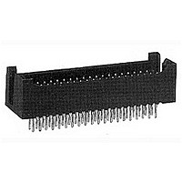
Conn Shrouded Header HDR 40 POS 2.54mm Solder ST Thru-Hole
Manufacturer
TE Connectivity
Type
Shrouded Headerr
Series
AMPMODU MOD II Seriesr
Datasheet
1.5-147323-4.pdf
(98 pages)
Specifications of 6-102567-2
Pitch
2.54 mm
Number Of Rows
2
Number Of Contacts
40
Gender
HDR
Contact Plating
Gold Over Nickel
Termination Method
Solder
Product Type
Headers - Shrouded
Contact Gender
Pin (Male)
Number Of Positions / Contacts
40
Row Spacing
2.54 mm
Mounting Style
Through Hole
Mounting Angle
Vertical
Termination Style
Solder
Housing Material
Thermoplastic, Glass Filled
Contact Material
Copper Alloy
Voltage Rating
250 VAC
Current Rating
3 A
Operating Temperature Range
- 65 C to + 105 C
Connector Type
Header
Pcb Mount Retention
Without
Pcb Mounting Orientation
Vertical
Termination Method To Pc Board
Through Hole - Solder
Post Size (mm [in])
0.64 [.025]
Contact - Rated Current (a)
3
Voltage (vac)
250
Dielectric Withstanding Voltage (v)
750
Termination Resistance (m?)
12
Insulation Resistance (m?)
1,000
Termination Post Length (mm [in])
4.57 [0.180]
Termination End Plating
Tin over Nickel
Header Type
Standard
Centerline (mm [in])
2.54 [0.100]
Number Of Positions
40
Row-to-row Spacing (mm [in])
2.54 [0.100]
Mating Retention
Without
Contact Protection
With
Contact Protection Type
Shrouded
Assembly Process Feature
None
Contact Type
Pin
Contact Plating, Mating Area, Material
Gold (15)
Contact Shape
Square
Contact Base Material
Copper Alloy
Connector Style
Plug
Mating Alignment
With
Mating Alignment Type
Guide Pin
Housing Color
Black
Ul Flammability Rating
UL 94V-0
Rohs/elv Compliance
RoHS compliant, ELV compliant
Lead Free Solder Processes
Wave solder capable to 240°C, Wave solder capable to 260°C, Wave solder capable to 265°C, Reflow solder capable to 245°C, Reflow solder capable to 260°C, Pin-in-Paste capable to 245°C, Pin-in-Paste capable to 260°C
Rohs/elv Compliance History
Always was RoHS compliant
Approved Standards
UL E28476, CSA LE7189
Pcb Thickness, Recommended (mm [in])
1.40 [0.055]
Temperature Range (°c)
-65 – +105
Contact Transmits (typical Application)
Signal (Data)
Lead Free Status / Rohs Status
Details


Closed Dual Entry, Side and
End Stackable Low Profile,
.100 x .100 [2.54 x 2.54]
Centerline, .150 [3.81] Tine
Spacing
Material and Finish
Housing — Glass-filled thermoplastic,
black, 94V-0 rated
Contacts — Phosphor bronze,
plated as follows:
Plating A — Duplex .000030 [0.00076]
gold on contact area, .000150-.000300
[0.00381-0.00762] matte tin on solder
area all over .000050 [0.00127] nickel
Plating B — Duplex .000010
[0.000254] gold on contact area,
.000150-.000300 [0.00381-0.00762]
matte tin on solder area all over .000050
[0.00127] nickel
Plating C — .000150-.000300
[0.00381-0.00762] matte tin on solder
leads, all over .000050 [0.00127] nickel
Related Product Data
Mateable Headers —
Refer to the Mating Post Selection
Guide — page 90
Performance Characteristics —
page 174
Technical Documents
Product Specification
108-25022
Application Specification
114-25018
Note: All part numbers are RoHS
Catalog 1307819
Revised 8-08
www.tycoelectronics.com
compliant.
— page 276
are metric equivalents.
Dimensions are in inches and
millimeters unless otherwise
specified. Values in brackets
[
.075
.060
1.90
AMPMODU Interconnection System
Mod. IV Receptacle Assemblies, Double-Row,
.100 x .100 [2.54 x 2.54] Centerline
[5.03]
Notes: 1. Tyco Electronics recommends mating gold or duplex plated headers with duplex plated receptacle assemblies.
.198
No. of
+.005
+0.13
- 0.00
Pos.
[2.54]
-.000
.100
10
12
14
16
18
20
22
24
26
28
30
32
34
36
38
40
2
4
6
8
]
for Bottom Entry or Pass Through Applications
2. To obtain the minimum mating post length, add .020 [0.51] (not including the post lead in chamfer) to
Typ.
Dia.
the maximum point-of-contact dimension, and .062 [1.57] for recommended board thickness if used in bot-
tom entry application.
*±.003 [±0.08] tolerances not to accumulate
Recommended PC Board Hole Layout
[1.27]
1.000 [25.40]
1.100 [27.94]
1.200 [30.48]
1.300 [33.02]
1.400 [35.56]
1.500 [38.10]
1.600 [40.64]
1.700 [43.18]
1.800 [45.72]
1.900 [48.26]
2.000 [50.80]
Max.
.050
Typ.
within one connector pattern.
.100 [2.54]
.200 [5.08]
.300 [7.62]
.400 [10.16]
.500 [12.70]
.600 [15.24]
.700 [17.78]
.800 [20.32]
.900 [22.86]
Dimensions are shown for
reference purposes only.
Specifications subject
to change.
A
Dimensions
[2.54]
.100*
B
A
Typ.
1.000 [25.40]
1.100 [27.94]
1.200 [30.48]
1.300 [33.02]
1.400 [35.56]
1.500 [38.10]
1.600 [40.64]
1.700 [43.18]
1.800 [45.72]
1.900 [48.26]
.100 [2.54]
.200 [5.08]
.300 [7.62]
.400 [10.16]
.500 [12.70]
.600 [15.24]
.700 [17.78]
.800 [20.32]
.900 [22.86]
—
B
[6.22]
USA: 1-800-522-6752
Canada: 1-905-470-4425
Mexico: 01-800-733-8926
C. America: 52-55-1106-0803
.245
Typ.
(Standoffs)
[2.54±0.08]
.100±.003
[0.51]
.020
Typ.
[2.54]
.100
Typ.
5-535542-1
5-535542-2
5-535542-3
5-535542-4
5-535542-5
5-535542-6
5-535542-7
5-535542-8
5-535542-9
6-535542-0
6-535542-1
6-535542-2
6-535542-3
6-535542-4
6-535542-5
6-535542-6
6-535542-7
6-535542-8
6-535542-9
7-535542-0
Plating A
[0.89±0.08]
.035±.003
(Localized Gold
Recommended PC Board Hole Layout
Plate Area)
Contact Plating/Part Nos.
[3.77]
[2.72]
.107
Dia. Typ.
.148
Typ.
Typ.
[2.54]
.100
Typ.
5-147095-1
5-147095-2
5-147095-3
5-147095-4
5-147095-5
5-147095-6
5-147095-7
5-147095-8
5-147095-9
6-147095-0
6-147095-1
6-147095-2
6-147095-3
6-147095-4
6-147095-5
6-147095-6
6-147095-7
6-147095-8
6-147095-9
7-147095-0
Plating B
for Top Entry
South America: 55-11-2103-6000
Hong Kong: 852-2735-1628
Japan: 81-44-844-8013
UK: 44-8706-080-208
Point of
Contact
B
5-147096-1
5-147096-2
5-147096-3
5-147096-4
5-147096-5
5-147096-6
5-147096-7
5-147096-8
5-147096-9
6-147096-0
6-147096-1
6-147096-2
6-147096-3
6-147096-4
6-147096-5
6-147096-6
6-147096-7
6-147096-8
6-147096-9
7-147096-0
Plating C
[3.30±0.25]
.130±.010
[3.81]
.150
Typ.
Typ.
[3.81]
.150
Typ.
183
5
Related parts for 6-102567-2
Image
Part Number
Description
Manufacturer
Datasheet
Request
R

Part Number:
Description:
PLUG, SOLARLOK, 6MM, NEG
Manufacturer:
TE Connectivity
Datasheet:
Part Number:
Description:
PLUG, SOLARLOK, 6MM, POS
Manufacturer:
TE Connectivity
Datasheet:

Part Number:
Description:
Electromechanical Relay SPDT 16A 12VDC 360Ohm Through Hole
Manufacturer:
TE Connectivity
Datasheet:
Part Number:
Description:
PLUG & SOCKET CONNECTOR, MALE, 1POS
Manufacturer:
TE Connectivity
Datasheet:


Part Number:
Description:
6-1415035-1
Manufacturer:
TE Connectivity
Datasheet:

Part Number:
Description:
Manufacturer:
TE Connectivity
Datasheet:

Part Number:
Description:
Res Thick Film 2512 6.8 Ohm 5% 1W ±350ppm/°C Molded SMD T/R
Manufacturer:
TE Connectivity
Datasheet:

Part Number:
Description:
SKT,SODIMM,144P,SDRAM3.3V,STD,T&R
Manufacturer:
TE Connectivity
Datasheet:

Part Number:
Description:
Manufacturer:
TE Connectivity
Datasheet:

Part Number:
Description:
Conn Shielded Circular Subminiature SKT 3 POS Solder ST Thru-Hole 3 Terminal 1 Port
Manufacturer:
TE Connectivity
Datasheet:

Part Number:
Description:
FASTIN-FASTON RECEP 6,35
Manufacturer:
TE Connectivity
Datasheet:

Part Number:
Description:
TERMINAL, SOCKET, FASTON, 18-15AWG
Manufacturer:
TE Connectivity
Datasheet:

Part Number:
Description:
Manufacturer:
TE Connectivity
Datasheet:
Part Number:
Description:
Manufacturer:
TE Connectivity
Datasheet: