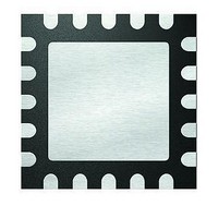
PIC16F1507-E/ML Microchip Technology, PIC16F1507-E/ML Datasheet - Page 17

PIC16F1507-E/ML
Manufacturer Part Number
PIC16F1507-E/ML
Description
3.5KB Flash, 128B RAM, 18 I/O, CLC, CWG, DDS, 10-bit ADC 20 QFN 4x4mm TUBE
Manufacturer
Microchip Technology
Series
PIC® 16Fr
Datasheets
1.PIC16F1507-EML.pdf
(266 pages)
2.PIC16F1507-EML.pdf
(26 pages)
3.PIC16F1507-EML.pdf
(40 pages)
Specifications of PIC16F1507-E/ML
Processor Series
PIC16
Core
PIC16F
Data Bus Width
8 bit
Program Memory Type
Flash
Program Memory Size
3.5 KB
Data Ram Size
128 B
Interface Type
ICSP
Maximum Clock Frequency
20 MHz
Number Of Programmable I/os
18
Number Of Timers
3
Operating Supply Voltage
2.3 V to 5.5 V
Maximum Operating Temperature
+ 125 C
Mounting Style
SMD/SMT
Package / Case
QFN-20
Minimum Operating Temperature
- 40 C
Operating Temperature Range
- 40 C to + 125 C
Supply Current (max)
30 uA
Core Processor
PIC
Core Size
8-Bit
Speed
20MHz
Connectivity
-
Peripherals
Brown-out Detect/Reset, POR, PWM, WDT
Number Of I /o
17
Eeprom Size
-
Ram Size
128 x 8
Voltage - Supply (vcc/vdd)
2.3 V ~ 5.5 V
Data Converters
A/D 12x10b
Oscillator Type
Internal
Operating Temperature
-40°C ~ 125°C
Lead Free Status / Rohs Status
Details
CLC Configuration Tool Overview
FIGURE 1-10:
COMMENT TEXT AREA
The button, Copy and Show is used to get a quick view of the register values for the
present configuration. When pressed, the boxes below the button will be filled with the
settings that correspond to the design. If multiple CLCs share similar configurations,
one CLC module can be designed and then pasted into another by clicking the Copy
and Show in the current module and then Paste in another CLC module. This will copy
all of the content from one CLC to another. The clipboard contents cannot be pasted to
any window outside of the CLC tool. The Clear button will reset all fields to their default
state.
2011 Microchip Technology Inc.
DS41597A-page 17


