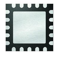
PIC16F1507-E/ML Microchip Technology, PIC16F1507-E/ML Datasheet - Page 19

PIC16F1507-E/ML
Manufacturer Part Number
PIC16F1507-E/ML
Description
3.5KB Flash, 128B RAM, 18 I/O, CLC, CWG, DDS, 10-bit ADC 20 QFN 4x4mm TUBE
Manufacturer
Microchip Technology
Series
PIC® 16Fr
Datasheets
1.PIC16F1507-EML.pdf
(266 pages)
2.PIC16F1507-EML.pdf
(26 pages)
3.PIC16F1507-EML.pdf
(40 pages)
Specifications of PIC16F1507-E/ML
Processor Series
PIC16
Core
PIC16F
Data Bus Width
8 bit
Program Memory Type
Flash
Program Memory Size
3.5 KB
Data Ram Size
128 B
Interface Type
ICSP
Maximum Clock Frequency
20 MHz
Number Of Programmable I/os
18
Number Of Timers
3
Operating Supply Voltage
2.3 V to 5.5 V
Maximum Operating Temperature
+ 125 C
Mounting Style
SMD/SMT
Package / Case
QFN-20
Minimum Operating Temperature
- 40 C
Operating Temperature Range
- 40 C to + 125 C
Supply Current (max)
30 uA
Core Processor
PIC
Core Size
8-Bit
Speed
20MHz
Connectivity
-
Peripherals
Brown-out Detect/Reset, POR, PWM, WDT
Number Of I /o
17
Eeprom Size
-
Ram Size
128 x 8
Voltage - Supply (vcc/vdd)
2.3 V ~ 5.5 V
Data Converters
A/D 12x10b
Oscillator Type
Internal
Operating Temperature
-40°C ~ 125°C
Lead Free Status / Rohs Status
Details
2.1
2.2
2.3
2.4
2011 Microchip Technology Inc.
INTRODUCTION
HIGHLIGHTS
EXAMPLE PROBLEM
PROPOSED SOLUTION
Chapter 2. Manchester Line Code Example
This example will use the information in Chapter 1. “CLC Configuration Tool Overview”
in solving a typical problem that can now be achieved with ease using the Configurable
Logic Cell Configuration Tool. It is recommended that the reader first understand how to
use the program before continuing.
This chapter discusses:
• Example Problem
• Proposed Solution
• Extended Solution
You want to encode a bit stream of a typical non-return-to-zero (NRZ) line code from a
certain device to a slimmer, more versatile Manchester line code. A Manchester line
code has advantages over the typical NRZ code in that Manchester encoding com-
bines the clock and data into one data stream. It has no DC component and is
self-clocking. A diagram of a potential setup is shown in Figure 2-1.
FIGURE 2-1:
Using only one CLC module on a PIC
be no limitation to the clock speed, since the CLC is not controlled by software. This
allows the CPU to focus on the main program without dealing with the encoding pro-
cess. This also saves the designer additional costs by not having to include more exter-
nal hardware to perform the same task.
The encoding process simply requires an XOR gate with the data and clock inputs. For
this design, a PIC16F1507 is used with its CLC2 module.
NRZ LINE CODE ENCODED TO A MANCHESTER CODE
CLC CONFIGURATION TOOL
®
device would accomplish this task. There would
USER’S GUIDE
DS41597A-page 19


