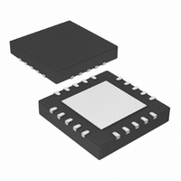
PIC24F16KA101T-I/MQ Microchip Technology, PIC24F16KA101T-I/MQ Datasheet - Page 28

PIC24F16KA101T-I/MQ
Manufacturer Part Number
PIC24F16KA101T-I/MQ
Description
16KB Flash, 2KB RAM, 512B EEPROM, 16 MIPS, 16 I/O,16-bit PIC24F Family, NanoWatt
Manufacturer
Microchip Technology
Series
PIC® XLP™ 24Fr
Datasheets
1.MA240017.pdf
(254 pages)
2.PIC24F04KA201-ISS.pdf
(48 pages)
3.PIC24F16KA101-ISS.pdf
(18 pages)
Specifications of PIC24F16KA101T-I/MQ
Core Processor
PIC
Core Size
16-Bit
Speed
32MHz
Connectivity
I²C, IrDA, SPI, UART/USART
Peripherals
Brown-out Detect/Reset, POR, PWM, WDT
Number Of I /o
18
Program Memory Size
16KB (5.5K x 24)
Program Memory Type
FLASH
Eeprom Size
512 x 8
Ram Size
1.5K x 8
Voltage - Supply (vcc/vdd)
1.8 V ~ 3.6 V
Data Converters
A/D 9x10b
Oscillator Type
Internal
Operating Temperature
-40°C ~ 85°C
Package / Case
20-VQFN
Lead Free Status / RoHS Status
Lead free / RoHS Compliant
Available stocks
Company
Part Number
Manufacturer
Quantity
Price
Part Number:
PIC24F16KA101T-I/MQ
Manufacturer:
MICROCHIP/微芯
Quantity:
20 000
PIC24FXXKAXXX
4.7.3
The FBS and FGS Configuration registers are special
Configuration registers which control the code
protection for the boot segment and general segment,
respectively. For each segment, two forms of code
protection are provided. One form prevents code
memory from being written (write protection), while the
other prevents it from being read (read protection).
The BWRP and GWRP bits control write protection and
the BSS0 and GSS0 bits control read protection.
When write protection is enabled, any programming
operation to code memory will fail. When read
protection is enabled, any read from code memory will
cause a 00h to be read, regardless of the actual
contents of code memory. Since the programming
TABLE 4-2:
DS39919A-page 28
BOREN<1:0>
BORV<1:0>
BSS0
BSZ<1:0>
BWRP
DEBUG
DSWDTEN
DSWCKSEL
Note 1:
Bit Field
2:
Applies only to the 28-pin device.
The MCLRE fuse can only be changed when using the V
from accidentally locking out the device from low-voltage test entry.
CODE-PROTECT CONFIGURATION
BITS
PIC24FXXKAXXX FAMILY CONFIGURATION BITS DESCRIPTION
FPOR<1:0>
FPOR<6:5>
FBS<3>
FBS<2:1>
FBS<0>
FICD<7>
FDS<7>
FDS<4>
Register
Brown-out Reset Enable bits
11 = Brown-out Reset enabled in hardware; SBOREN bit disabled
10 = Brown-out Reset enabled only while device is active and disabled in
01 = Brown-out Reset controlled with the SBOREN bit setting
00 = Brown-out Reset disabled in hardware; SBOREN bit disabled
Brown-out Reset Voltage bits
11 = V
10 = V
01 = V
00 = Downside protection on POR enabled – “Zero-power” selected
Boot Segment Program Flash Code Protection bit
1 = No protection
0 = Standard security enabled
Boot Segment Program Flash Size Selection bits
11 = No boot program Flash segment
10 = Boot program Flash segment starts at 200h, ends at 000AFEh
01 = Boot program Flash segment starts at 200h, ends at 0015FEh
00 = Reserved
Boot Segment Program Flash Write Protection bit
1 = Boot segment may be written
0 = Boot segment is write-protected
Background Debugger Enable bit
1 = Background debugger disabled
0 = Background debugger functions enabled
Deep Sleep Watchdog Timer Enable bit
1 = DSWDT enabled
0 = DSWDT disabled
DSWDT Reference Clock Select bit
1 = DSWDT uses LPRC as reference clock
0 = DSWDT uses SOSC as reference clock
Advance Information
Sleep; SBOREN bit disabled
BOR
BOR
BOR
set to 1.8V min
set to 2.0V min
set to 2.7V min
executive always verifies what it programs, attempting
to program code memory with read protection enabled
also results in failure.
It is imperative that all code protection bits should be ‘1’
while the device is being programmed, and verified.
Only after the device is programmed and verified
should any of the above bits be programmed to ‘0’ (see
Section 4.7 “Configuration Bits Programming”).
Note:
PP
-Based Test mode entry. This prevents a user
Description
All bits in the FBS and FGS Configuration
registers can only be programmed to a
value of ‘0‘.Bulk Erasing the chip is the
only way to reprogram code-protect bits
from on (‘0’) to off (‘1’).
© 2008 Microchip Technology Inc.


