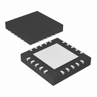
PIC24F16KA101T-I/MQ Microchip Technology, PIC24F16KA101T-I/MQ Datasheet - Page 35

PIC24F16KA101T-I/MQ
Manufacturer Part Number
PIC24F16KA101T-I/MQ
Description
16KB Flash, 2KB RAM, 512B EEPROM, 16 MIPS, 16 I/O,16-bit PIC24F Family, NanoWatt
Manufacturer
Microchip Technology
Series
PIC® XLP™ 24Fr
Datasheets
1.MA240017.pdf
(254 pages)
2.PIC24F04KA201-ISS.pdf
(48 pages)
3.PIC24F16KA101-ISS.pdf
(18 pages)
Specifications of PIC24F16KA101T-I/MQ
Core Processor
PIC
Core Size
16-Bit
Speed
32MHz
Connectivity
I²C, IrDA, SPI, UART/USART
Peripherals
Brown-out Detect/Reset, POR, PWM, WDT
Number Of I /o
18
Program Memory Size
16KB (5.5K x 24)
Program Memory Type
FLASH
Eeprom Size
512 x 8
Ram Size
1.5K x 8
Voltage - Supply (vcc/vdd)
1.8 V ~ 3.6 V
Data Converters
A/D 9x10b
Oscillator Type
Internal
Operating Temperature
-40°C ~ 85°C
Package / Case
20-VQFN
Lead Free Status / RoHS Status
Lead free / RoHS Compliant
Available stocks
Company
Part Number
Manufacturer
Quantity
Price
Part Number:
PIC24F16KA101T-I/MQ
Manufacturer:
MICROCHIP/微芯
Quantity:
20 000
5.2.4
The commands supported by the programming
executive are described in Section 5.2.5 “SCHECK
Command”
Command”.
5.2.5
The SCHECK command instructs the programming
executive to merely generate a response. This
command is used as a “Sanity Check” to verify if the
programming executive is operational.
Expected Response (2 words):
5.2.6
The READC command instructs the programming
executive to read N or Device ID registers, starting from
the 24-bit address specified by Addr_MSB and
Addr_LS.
© 2008 Microchip Technology Inc.
15
Opcode
Length
15
Opcode
Length
N
Addr_MSB
Addr_LS
Note:
Note:
Opcode
Field
1000h
0002h
Opcode
Field
12 11
12 11
COMMAND DESCRIPTIONS
SCHECK COMMAND
This instruction is provided for development
purposes only; this is not required for
programming.
READC COMMAND
This command can only be used to read
8-bit or 16-bit data.
N
1h
3h
Number of 8-bit Device ID registers to
read (max. of 256).
MSb of 24-bit source address.
Least Significant 16 bits of 24-bit
source address.
through
0h
1h
Addr_LS
8 7
Section 5.2.13
Description
Description
Length
Length
Addr_MSB
Advance Information
“QVER
0
0
When this command is used to read the Device ID
registers, the upper byte in every data word returned by
the programming executive is 00h and the lower byte
contains the Device ID register value.
Expected Response (4 + 3 * (N – 1)/2 words for N odd):
5.2.7
The READD command instructs the programming
executive to read N 16-bit words from data EEPROM
memory, starting from the 24-bit address specified by
Addr_MSB and Addr_LS.
Expected Response (N + 2 words):
15
Opcode
Length
Reserved0
N
Reserved1
Addr_MSB
Addr_LS
Note:
Note:
Opcode
1100h
2 + N
Device ID Register 1
...
Device Register N
1E00h
2 + N
Data word 1
...
Data word N
Field
Reserved0
Reserved1
PIC24FXXKAXXX
12 11
Reading unimplemented memory will
cause the programming executive to
reset. Ensure that only memory locations
present on a particular device are
accessed.
READD COMMAND
This command can only be used to read
16-bit data.
Eh
4h
0h
Number of 16-bit words to read
(max of 256).
0h
MSb of 24-bit source address.
Least Significant 16 bits of 24-bit
source address.
Addr_LS
8 7
Description
Length
Addr_MSB
DS39919A-page 35
N
0


