PIC24FV16KA302-E/SP Microchip Technology, PIC24FV16KA302-E/SP Datasheet - Page 140
PIC24FV16KA302-E/SP
Manufacturer Part Number
PIC24FV16KA302-E/SP
Description
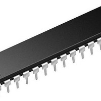
16KB Flash, 2KB RAM, 512B EEPROM, 16 MIPS, 12-bit ADC, CTMU, 5V 28 SPDIP .300in
Manufacturer
Microchip Technology
Series
PIC® XLP™ 24Fr
Datasheet
1.PIC24F16KA301T-ISO.pdf
(320 pages)
Specifications of PIC24FV16KA302-E/SP
Processor Series
PIC24FV
Core
PIC
Data Bus Width
16 bit
Program Memory Type
Flash
Program Memory Size
16 KB
Data Ram Size
2 KB
Maximum Operating Temperature
+ 125 C
Mounting Style
Through Hole
Package / Case
SPDIP-28
Development Tools By Supplier
MPLAB IDE Software
Minimum Operating Temperature
- 40 C
Core Processor
PIC
Core Size
16-Bit
Speed
32MHz
Connectivity
I²C, IrDA, LIN, SPI, UART/USART
Peripherals
Brown-out Detect/Reset, HLVD, POR, PWM, WDT
Number Of I /o
23
Eeprom Size
512 x 8
Ram Size
2K x 8
Voltage - Supply (vcc/vdd)
2 V ~ 5.5 V
Data Converters
A/D 13x12b
Oscillator Type
Internal
Operating Temperature
-40°C ~ 125°C
Lead Free Status / Rohs Status
Details


PIC24FV32KA304 FAMILY
11.1.1
In addition to the PORT, LAT and TRIS registers for
data control, each port pin can also be individually
configured for either digital or open-drain output. This is
controlled by the Open-Drain Control register, ODCx,
associated with each port. Setting any of the bits
configures the corresponding pin to act as an
open-drain output.
The maximum open-drain voltage allowed is the same
as the maximum V
11.2
The use of the ANS and TRIS registers control the
operation of the A/D port pins. The port pins that are
desired
corresponding TRIS bit set (input). If the TRIS bit is
cleared (output), the digital output level (V
will be converted.
REGISTER 11-1:
DS39995B-page 140
bit 15
bit 7
Legend:
R = Readable bit
-n = Value at POR
bit 15-4
bit 3-0
U-0
U-0
—
—
Configuring Analog Port Pins
as
OPEN-DRAIN CONFIGURATION
Unimplemented: Read as ‘0’
ANSA<3:0>: Analog Select Control bits
1 = Digital input buffer is not active (use for analog input)
0 = Digital input buffer is active
analog
IH
U-0
U-0
—
—
specification.
ANSA: ANALOG SELECTION (PORTA)
inputs
U = Unimplemented bit, read as ‘0’
W = Writable bit
‘1’ = Bit is set
must
U-0
U-0
—
—
have
OH
or V
U-0
U-0
their
—
—
OL
)
HSC = Hardware Settable/Clearable bit
‘0’ = Bit is cleared
ANSA3
R/W-1
When reading the PORT register, all pins configured as
analog input channels will read as cleared (a low level).
Analog levels on any pin that is defined as a digital
input (including the ANx pins) may cause the input
buffer to consume current that exceeds the device
specifications.
11.2.1
I/O pins with shared analog functionality, such as ADC
inputs and comparator inputs, must have their digital
inputs shut off when analog functionality is used. Note
that analog functionality includes an analog voltage
being applied to the pin externally.
To allow for analog control, the ANSx registers are
provided. There is one ANS register for each port
(ANSA, ANSB and ANSC). Within each ANSx register,
there is a bit for each pin that shares analog
functionality with the digital I/O functionality.
If a particular pin does not have an analog function, that
bit is unimplemented. See
for implementation.
U-0
—
ANALOG SELECTION REGISTER
ANSA2
R/W-1
U-0
—
2011 Microchip Technology Inc.
Register 11-1
x = Bit is unknown
ANSA1
R/W-1
U-0
—
to
Register 11-3
ANSA0
R/W-1
U-0
—
bit 8
bit 0
Related parts for PIC24FV16KA302-E/SP
Image
Part Number
Description
Manufacturer
Datasheet
Request
R

Part Number:
Description:
Manufacturer:
Microchip Technology Inc.
Datasheet:
Part Number:
Description:
Manufacturer:
Microchip Technology Inc.
Datasheet:
Part Number:
Description:
Manufacturer:
Microchip Technology Inc.
Datasheet:
Part Number:
Description:
Manufacturer:
Microchip Technology Inc.
Datasheet:
Part Number:
Description:
Manufacturer:
Microchip Technology Inc.
Datasheet:
Part Number:
Description:
Manufacturer:
Microchip Technology Inc.
Datasheet:
Part Number:
Description:
Manufacturer:
Microchip Technology Inc.
Datasheet:
Part Number:
Description:
Manufacturer:
Microchip Technology Inc.
Datasheet: