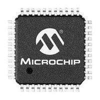
PIC24FV32KA304-E/PT Microchip Technology, PIC24FV32KA304-E/PT Datasheet - Page 315

PIC24FV32KA304-E/PT
Manufacturer Part Number
PIC24FV32KA304-E/PT
Description
32KB Flash, 2KB RAM, 512B EEPROM, 16 MIPS, 12-bit ADC, CTMU, 5V 44 TQFP 10x10x1m
Manufacturer
Microchip Technology
Series
PIC® XLP™ 24Fr
Datasheet
1.PIC24F16KA301T-ISO.pdf
(320 pages)
Specifications of PIC24FV32KA304-E/PT
Processor Series
PIC24FV
Core
PIC
Data Bus Width
16 bit
Program Memory Type
Flash
Program Memory Size
32 KB
Data Ram Size
2 KB
Maximum Operating Temperature
+ 125 C
Mounting Style
SMD/SMT
Package / Case
TQFP-44
Development Tools By Supplier
MPLAB IDE Software
Minimum Operating Temperature
- 40 C
Core Processor
PIC
Core Size
16-Bit
Speed
32MHz
Connectivity
I²C, IrDA, LIN, SPI, UART/USART
Peripherals
Brown-out Detect/Reset, HLVD, POR, PWM, WDT
Number Of I /o
38
Eeprom Size
512 x 8
Ram Size
2K x 8
Voltage - Supply (vcc/vdd)
2 V ~ 5.5 V
Data Converters
A/D 16x12b
Oscillator Type
Internal
Operating Temperature
-40°C ~ 125°C
Lead Free Status / Rohs Status
Details
Available stocks
Company
Part Number
Manufacturer
Quantity
Price
Company:
Part Number:
PIC24FV32KA304-E/PT
Manufacturer:
MICROCHIP
Quantity:
12 000
Company:
Part Number:
PIC24FV32KA304-E/PT
Manufacturer:
Microchip Technology
Quantity:
10 000
O
On-Chip Voltage Regulator .............................................. 248
Oscillator Configuration
Output Compare
P
Packaging
Pinout Descriptions ............................................................ 18
Power-Saving ................................................................... 137
Power-Saving Features ................................................... 127
Product Identification System .......................................... 319
Program and Data Memory
Program and Data Memory Spaces
Program Memory
Program Verification ........................................................ 250
Pulse-Width Modulation (PWM) Mode ............................. 158
Pulse-Width Modulation. See PWM.
PWM
R
Reader Response ............................................................ 318
Register Maps
2011 Microchip Technology Inc.
Clock Switching ........................................................ 123
Configuration Values for Clock Selection ................. 118
CPU Clocking Scheme ............................................ 118
Initial Configuration on POR .................................... 118
Reference Clock Output ........................................... 124
32-Bit Mode .............................................................. 155
Operations ............................................................... 157
Subcycle Resolution ................................................ 160
Synchronous and Trigger Modes ............................. 155
Details ...................................................................... 292
Marking .................................................................... 289
Clock Frequency, Clock Switching ........................... 127
Coincident Interrupts ................................................ 128
Instruction-Based Modes ......................................... 127
Selective Peripheral Control .................................... 137
Ultra Low-Power Wake-up ....................................... 133
Voltage Regulator-Based ......................................... 135
Access Using Table Instructions ................................ 55
Program Space Visibility ............................................ 57
Addressing ................................................................. 53
Interfacing .................................................................. 53
Address Space ........................................................... 37
Device Configuration Words ...................................... 38
Hard Memory Vectors ................................................ 38
Memory Map .............................................................. 37
Organization ............................................................... 38
Duty Cycle and Period ............................................. 159
A/D Converter (ADC) ................................................. 49
Analog Select ............................................................. 50
Clock Control ............................................................. 51
CPU Core ................................................................... 41
CRC ........................................................................... 51
CTMU ......................................................................... 50
Deep Sleep ................................................................ 51
Sequence ......................................................... 123
Deep Sleep ...................................................... 128
Idle ................................................................... 128
Sleep ................................................................ 127
Deep Sleep Mode ............................................ 135
Fast Wake-up Sleep Mode .............................. 135
Retention Sleep Mode ..................................... 135
Run Mode ........................................................ 135
Sleep (Standby) Mode ..................................... 135
PIC24FV32KA304 FAMILY
Registers
I
ICN ............................................................................ 42
Input Capture ............................................................. 44
Interrupt Controller ..................................................... 43
NVM ........................................................................... 52
Output Compare ........................................................ 45
Pad Configuration ...................................................... 48
PMD ........................................................................... 52
PORTA ...................................................................... 47
PORTB ...................................................................... 47
PORTC ...................................................................... 48
Real-Time Clock and Calendar (RTCC) .................... 50
SPI ............................................................................. 47
Timer ......................................................................... 44
UART ......................................................................... 46
Ultra Low-Power Wake-up ......................................... 52
AD1CHITH (A/D Scan Compare Hit,
AD1CHITH (A/D Scan Compare Hit, Low Word) ..... 220
AD1CHS (A/D Sample Select) ................................ 219
AD1CON1 (A/D Control 1) ....................................... 215
AD1CON2 (A/D Control 2) ....................................... 216
AD1CON3 (A/D Control 3) ....................................... 217
AD1CON5 (A/D Control 5) ....................................... 218
AD1CTMENH (CTMU Enable, High Word) ............. 222
AD1CTMENL (CTMU Enable, Low Word) ............... 222
ADCSSH (A/D Input Scan Select, High Word) ........ 221
ADCSSL (A/D Input Scan Select, Low Word) ......... 221
ALCFGRPT (Alarm Configuration) .......................... 194
ALMINSEC (Alarm Minutes and Seconds
ALMTHDY (Alarm Month and Day Value) ............... 197
ALWDHR (Alarm Weekday and Hours Value) ........ 197
ANSA (Analog Selection, PORTA) .......................... 140
ANSB (Analog Selection, PORTB) .......................... 141
ANSC (Analog Selection, PORTC) .......................... 141
CLKDIV (Clock Divider) ........................................... 121
CMSTAT (Comparator Status) ................................ 228
CMxCON (Comparator x Control) ........................... 227
CORCON (CPU Control) ........................................... 35
CORCON (CPU Core Control) .................................. 84
CRCCON1 (CRC Control 1) .................................... 206
CRCCON2 (CRC Control 2) .................................... 207
CRCXORH (CRC XOR Polynomial, High Byte) ...... 208
CRCXORL (CRC XOR Polynomial, Low Byte) ........ 207
CTMUCON (CTMU Control 1) ................................. 234
CTMUCON2 (CTMU Control 2) ............................... 235
CTMUICON (CTMU Current Control) ...................... 237
CVRCON (Comparator Voltage
DEVID (Device ID) ................................................... 246
DEVREV (Device Revision) ..................................... 247
DSCON (Deep Sleep Control) ................................. 131
DSWAKE (Deep Sleep Wake-up Source) ............... 132
FBS (Boot Segment Configuration) ......................... 239
FDS (Deep Sleep Configuration) ............................. 245
FGS (General Segment Configuration) ................... 240
FICD (In-Circuit Debugger Configuration) ............... 244
FOSC (Oscillator Configuration) .............................. 241
FOSCSEL (Oscillator Selection Configuration) ....... 240
FPOR (Reset Configuration) ................................... 243
FWDT (Watchdog Timer Configuration) .................. 242
HLVDCON (High/Low-Voltage Detect Control) ....... 210
I2CxMSK (I2Cx Slave Mode Address Mask) ........... 180
2
C ............................................................................. 46
High Word) ...................................................... 220
Value) .............................................................. 198
Reference Control) .......................................... 230
DS39995B-page 315


