88 865 155 Crouzet USA, 88 865 155 Datasheet - Page 11
88 865 155
Manufacturer Part Number
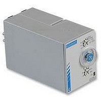
88 865 155
Description
TIMER, FLIP/FLOP
Manufacturer
Crouzet USA
Datasheet
1.88_865_385.pdf
(12 pages)
Specifications of 88 865 155
Contact Configuration
SPCO
Nom Input Voltage
240VAC
Delay Time Range
0.1s To 100h
Relay Mounting
DIN Rail
Svhc
No SVHC (18-Jun-2010)
Adjustment Type
Screwdriver Slot
Coil Voltage Vdc Nom
24V
Contact Current
RoHS Compliant
Contact Current Ac Max
8A
Rohs Compliant
Yes


U : Supply
R : Output or load relay
T: Timing
Function A
Delay on energisation
Single timing cycle which
begins on energisation.
The output changes state after timing.
Function Ac
Timing after closing and opening
of control contact
After energisation, closure of the control
contact causes the timing period T
to commence and output relay R
(or the load) changes state at the end of
this interval. When contact C (Y1) opens,
relay R resets after a second timing period T.
Function Ad
Timing after closing of control contact
After energisation, closure of the control
contact causes the timing period T to
commence and output relay R changes
state at the end of this interval.
Function Ah
On short cycle after closing of control contact
After energisation, closure of the control
contact causes the timing period T to
commence and output relay R changes state
at the end of this period. After a further period
of time: T the relay returns to its original state.
Function At
Timing on energisation with memory
Provides a cumulative time for contact opening.
The output changes states at the
end of the set time.
Function B
Timing on impulse one shot
On pulse (with constant supply)
After energisation; a pulse (≥ 50 ms)
or a maintained control contact will
cause the output to change state
which reverts to the rest position
at the end of timing.
N.B. : this process enables
shortening or lengthening of a signal.
2 relays timed or
1 relay timed and 1 instantaneous
2 relays timed or
1 relay timed and 1
instantaneous
2 relays timed or
1 relay timed and 1 instantaneous
2 relays timed or
1 relay timed and 1 instantaneous
C (Y1) : Control contact
∞
: indefinite
R2 INST
R2 Inst.
R2 Inst.
R1/R2
R1/R2
R1/R2
R2 Inst.
R1/R2
FUNCTION DIAGRAMS FOR TIMERS
1 relay
U
R
1 relay
1 relay
U
C
R
U
U
C
R
U
C
U
C
U
C
R
1 relay
U
C
R
1 relay
1 relay
U
C
R
U
C
∞
T
T
t1
T
t1
T
T
T
T
T
T
T = t1+t2
T = t1+t2
t2
t2
T
T
T
T
T
72
Function Bw
Pulse output (adjustable)
Output relay R (or the load) changes state,
and remains in the changed-over state
for the timing period, both when
control contact C (Y1) closes
and when it opens.
N.B. This is complementary to function A.
Function Ht
Delay on energisation with memory
Provides a cumulative time for
contact opening. On energisation,
the output changes state,
remains in that state for the duration of timing
and resets at the end of the single cycle.
Function C
Timing after impulse
Delay OFF (with constant supply)
After energisation, once the control contact
is closed the output state changes.
Timing will only begin on the
re-opening of this control contact (one shot).
Relay R returns to its initial position
at the end of the timing period.
Function D or Di
Flip-flop
Repetitive cycle which switches the output
alternately between the rest and
operating position for equal time bases.
T1 + T2 = T total
D = Pause Start
Di = Pulse Start
Function H
Timing on energisation
Interval timer - one shot
On energisation, the output changes state,
remains in that state for the duration of
timing and resets at the end of the single cycle.
2 relays timed or
1 relay timed and 1 instantaneous
2 relays timed or
1 relay timed and 1 instantaneous
2 relays timed or
1 relay timed and 1 instantaneous
2 relays timed or
1 relay timed and 1 instantaneous
R2 inst.
R2 Inst.
R1/R2
R2 Inst.
R1/R2
R1/R2
U
C
R
1 relay
1 relay
U
R
U
1 relay
U
C
R
U
C
R
U
R
U
C
R
U
C
U
C
1 relay
1 relay
∞
TIMERS
T T
T
T
T
T
t1
t1
T
T
T = t1+t2
T = t1+t2
t2
t2
T
T
Related parts for 88 865 155
Image
Part Number
Description
Manufacturer
Datasheet
Request
R

Part Number:
Description:
TIMER, MULTIFUNCTION
Manufacturer:
Crouzet USA
Datasheet:
Part Number:
Description:
Electromechanical Multifunction Timer
Manufacturer:
Crouzet USA
Datasheet:

Part Number:
Description:
Electromechanical Multifunction Timer
Manufacturer:
Crouzet USA
Datasheet:

Part Number:
Description:
MULTI-FUNCTION TIMER, DPDT, 100H, 230VAC
Manufacturer:
Crouzet USA
Datasheet:
Part Number:
Description:
TIMER, MULTIFUNCTION
Manufacturer:
Crouzet USA
Datasheet:

Part Number:
Description:
TIMER, CAGE CLAMP, MURC3
Manufacturer:
Crouzet USA
Datasheet:

Part Number:
Description:
LAMP, INCAND, BAYONET, 6.8V, 12.98W
Manufacturer:
SPC TECHNOLOGY
Datasheet:

Part Number:
Description:
Circular MIL / Spec Connectors JT Series MIL-DTL-38999 II
Manufacturer:
Amphenol

Part Number:
Description:
M3 DISPLAY KIT, 12 I/O, 230VAC
Manufacturer:
Crouzet USA
Datasheet:
Part Number:
Description:
M3 DISPLAY KIT, 20 I/O, 24VDC
Manufacturer:
Crouzet USA
Datasheet:

Part Number:
Description:
Controller; CTD46 Dual Display Temperature, 1/16 DIN, NEMA 4X, 110/220VAC
Manufacturer:
Crouzet USA
Datasheet:

Part Number:
Description:
11R1084
Manufacturer:
Crouzet USA
Datasheet:
Part Number:
Description:
11R1086
Manufacturer:
Crouzet USA
Datasheet:
Part Number:
Description:
11R1087
Manufacturer:
Crouzet USA
Datasheet:
Part Number:
Description:
11R1089
Manufacturer:
Crouzet USA
Datasheet: