HDSP2114S OSRAM Opto Semiconductors Inc, HDSP2114S Datasheet - Page 14
HDSP2114S
Manufacturer Part Number
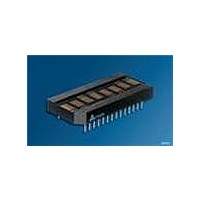
HDSP2114S
Description
LED Displays 5x7 Hi-Eff Green 0.2 , 8-CHARACTER
Manufacturer
OSRAM Opto Semiconductors Inc
Series
Intelligent Display®r
Datasheet
1.HDSP2110S.pdf
(16 pages)
Specifications of HDSP2114S
Display Type
Dot Matrix
Emitting Color
Hi-Eff. Green
Number Of Digits
8
Digit Size (in)
.2in
Viewing Area Height (mm)
4.81mm
Viewing Area Length (mm)
2.85mm
Package Type
Panel
Operating Supply Voltage (min)
4.5V
Operating Supply Voltage (typ)
5V
Operating Supply Voltage (max)
5.5V
Operating Temperature Classification
Industrial
Operating Temp Range
-40C to 85C
Mounting
Through Hole
Pin Count
28
Total Thickness (mm)
5.31mm
Opto Display Type
Panel
Pattern Type
Dot Matrix
Millicandela Rating
200µcd
Size / Dimension
1.70" L x 0.77" W x 0.21" H (42.67mm x 19.58mm x 5.31mm)
Color
Green
Configuration
5 x 7
Character Size
0.2 in
Illumination Color
High Efficiency Green
Wavelength
568 nm
Maximum Operating Temperature
+ 85 C
Minimum Operating Temperature
- 40 C
Luminous Intensity
510 ucd
Viewing Area (w X H)
2.85 mm x 4.81 mm
Lead Free Status / RoHS Status
Compliant
Voltage - Forward (vf) Typ
-
Internal Connection
-
Lead Free Status / Rohs Status
Details
Other names
Q68000A8564
Available stocks
Company
Part Number
Manufacturer
Quantity
Price

Part Number:
HDSP2114S-24
Manufacturer:
SIEMENS/西门子
Quantity:
20 000


Displaying User Defined Character Example
Load character “A” into UDC-5 and then display it in digit 2
Logic levels: 0=Low, 1=High, X=Don‘t care
RST
0
1
1
1
1
1
1
1
1
1
Electrical and Mechanical Considerations
Voltage Transient Suppression
For best results power the display and the components that inter-
face with the display to avoid logic inputs higher than V
tionally, the LEDs may cause transients in the power supply line
while they change display states. The common practice is to place
a parallel combination of a 0.01 µF and a 22 µF capacitor between
V
ESD Protection
The input protection structure of the HDSP211XS provides signifi-
cant protection against ESD damage. It is capable of withstanding
discharges greater than 2.0 kV. Take all the standard precautions,
normal for CMOS components. These include properly grounding
personnel, tools, tables, and transport carriers that come in con-
tact with unshielded parts. If these conditions are not, or cannot be
met, keep the leads of the device shorted together or the parts in
antistatic packaging.
Soldering Considerations
The HDSP211XS can be hand soldered with SN63 solder using a
grounded iron set to 260°C.
Wave soldering is also possible following these conditions:
Preheat that does not exceed 93°C on the solder side of the PC
board or a package surface temperature of 85°C. Water soluble
organic acid flux (except carboxylic acid) or rosin-based RMA flux
without alcohol can be used.
Direct contact with alcohol or alcohol vapor will cause degradation
of the package.
Wave temperature of 245°C ±5°C with a dwell between 1.5 sec.
to 3.0 sec. Exposure to the wave should not exceed tempera-
tures above 260°C for five seconds at 0.063" below the seating
plane. The packages should not be immersed in the wave.
2006-01-23
CC
and GND for all display packages.
HSDP2110S, HSDP2111S, HSDP2112S, HSDP2113S, HSDP2114S, HSDP2115S
CE
X
0
0
0
0
0
0
0
0
0
WR
1
0
0
0
0
0
0
0
0
0
RD
1
1
1
1
1
1
1
1
1
1
FL
1
1
1
1
1
1
1
1
1
1
A4
X
0
0
0
0
0
0
0
0
1
A3
X
0
1
1
1
1
1
1
1
1
A2
X
X
0
0
0
0
1
1
1
0
A1
X
X
0
0
1
1
0
0
1
1
A0
X
X
0
1
0
1
0
1
0
0
D7
X
X
X
X
X
X
X
X
X
1
CC
. Addi-
D6
X
X
X
X
X
X
X
X
X
X
D5
X
X
X
X
X
X
X
X
X
X
14
D4
X
X
0
1
1
1
1
1
1
X
Post Solder Cleaning Procedures
The least offensive cleaning solution is hot D.I. water (60°C) for
less than 15 minutes. Addition of mild saponifiers is acceptable. Do
not use commercial dishwasher detergents.
For faster cleaning, solvents may be used. Exercise care in choos-
ing solvents as some may chemically attack the nylon package.
Maximum exposure should not exceed two minutes at elevated
temperatures. Acceptable solvents are TF (trichorotrifluorethane),
TA, 111 Trichloroethane, and unheated acetone.
Note:
1)
Unacceptable solvents contain alcohol, methanol, methylene
chloride, ethanol, TP35, TCM, TMC, TMS+, TE, or TES. Since
many commercial mixtures exist, contact a solvent vendor for
chemical composition information. Some major solvent manu-
facturers are: Allied Chemical Corporation, Specialty Chemical
Division, Morristown, NJ; Baron-Blakeslee, Chicago, IL; Dow
Chemical, Midland, MI; E.I. DuPont de Nemours & Co., Wilm-
ington, DE.
For further information refer to Appnotes 18 and 19 at
www.osram-os.com
An alternative to soldering and cleaning the display modules is to
use sockets. Naturally, 28 pin DIP sockets .600" wide with .100"
centers work well for single displays. Multiple display assemblies
are best handled by longer SIP sockets or DIP sockets when avail-
able for uniform package alignment. Socket manufacturers are
Aries Electronics, Inc., Frenchtown, NJ; Garry Manufacturing, New
Brunswick, NJ; Robinson-Nugent, New Albany, IN; and Samtec
Electronic Hardward, New Albany, IN.
For further information refer to Appnote 22 at www.osram-os.com
Acceptable commercial solvents are: Basic TF, Arklone, P.
Genesolv, D. Genesolv DA, Blaco-Tron TF and Blaco-Tron TA.
D3
X
0
1
0
0
1
0
0
0
0
D2
X
1
1
0
0
1
0
0
0
1
D1
X
0
1
0
0
1
0
0
0
0
D0
X
1
0
1
1
1
1
1
1
1
Operation
Reset. No Read/Write
Within 3 Clock Cycles
Select UDC-5
Write into Row 1 of UDC-5
Write into Row 2 of UDC-5
Write into Row 3 of UDC-5
Write into Row 4 of UDC-5
Write into Row 5 of UDC-5
Write into Row 6 of UDC-5
Write into Row 7 of UDC-5
Write UDC-5 into Digit 2
(1)
Display
All Blank
All Blank
All Blank
All Blank
All Blank
All Blank
All Blank
All Blank
All Blank
(Digit 2) A
Related parts for HDSP2114S
Image
Part Number
Description
Manufacturer
Datasheet
Request
R

Part Number:
Description:
INTELLIGENT DISP 4CHAR 5X7 HERED
Manufacturer:
OSRAM Opto Semiconductors Inc
Datasheet:

Part Number:
Description:
DISPLAY 8DIGIT CERAMIC GREEN
Manufacturer:
OSRAM Opto Semiconductors Inc
Datasheet:

Part Number:
Description:
EMITTER IR 950NM 5MM SMD RADIAL
Manufacturer:
OSRAM Opto Semiconductors Inc
Datasheet:

Part Number:
Description:
LED TOPLED GREEN 570NM 2-PLCC
Manufacturer:
OSRAM Opto Semiconductors Inc
Datasheet:

Part Number:
Description:
INTERRUPTER RELFECT W/FILTR SMD
Manufacturer:
OSRAM Opto Semiconductors Inc
Datasheet:

Part Number:
Description:
LED Displays 5x7 Green 0.145 , 4-CHARACTER
Manufacturer:
OSRAM Opto Semiconductors Inc
Datasheet:

Part Number:
Description:
Q65110A4321_SIDELED PURE GREEN EOL150407
Manufacturer:
OSRAM Opto Semiconductors Inc
Datasheet:
Part Number:
Description:
Q65110A1202_RO DETECTOR 3/5MM_TR_RO
Manufacturer:
OSRAM Opto Semiconductors Inc
Datasheet:

Part Number:
Description:
PHOTODIODE 900NM 3MM W/FILTER
Manufacturer:
OSRAM Opto Semiconductors Inc
Datasheet:
Part Number:
Description:
INTELLIGENT DISP 4CHAR 5X7 HERED
Manufacturer:
OSRAM Opto Semiconductors Inc
Datasheet:
Part Number:
Description:
LED TOPLED GREEN 570NM 2-PLCC
Manufacturer:
OSRAM Opto Semiconductors Inc
Datasheet:
Part Number:
Description:
PHOTODIODE 900NM 3MM W/FILTER
Manufacturer:
OSRAM Opto Semiconductors Inc
Datasheet:

Part Number:
Description:
PHOTODIODE 850NM THRU-HOLE
Manufacturer:
OSRAM Opto Semiconductors Inc
Datasheet:

Part Number:
Description:
PHOTODIODE 880NM W/FILTER SMD
Manufacturer:
OSRAM Opto Semiconductors Inc
Datasheet: