SF2008D RFM, SF2008D Datasheet
SF2008D
Specifications of SF2008D
Available stocks


Related parts for SF2008D


SF2008D Summary of contents
Page 1
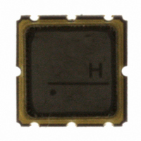
... RF Monolithics, Inc. SF2008D 930.5 MHz SAW Filter Units dBm VDC °C SM3838-6 Min Typ Max 930.5 4.5 2 -20 + j57 ohm 50 - j57 ohm SM3838-6 3.8 x 3.8 mm Nominal Footprint 455, YWWS 1000 Pieces/Reel 3000 Pieces/Reel Units MHz dB dB P-P dB °C Page SF2008D - 6/11/09 ...
Page 2
... S21 Wide Span S21 Narrow Span www.RFM.com E-mail: info@rfm.com ©2009 by RF Monolithics, Inc. Page SF2008D - 6/11/09 ...
Page 3
... Electrical Connections Terminals All others Materials O Ceramic 2 3 BOTTOM VIEW Max 0.16 0.16 0.067 0.05 0.110 0.043 0.83 0.028 0.075 Page SF2008D - 6/11/09 ...
Page 4
... COMPONENT ORIENTATION and DIMENSIONS 2.0 4.0 PIN # Pitch Ko USER DIRECTION OF FEED SECTION B-B “B “ Nominal Size Quantity Per Reel Inches millimeters 7 178 13 330 Carrier Tape Dimensions Pitch W A 1.50 A R0.5 (MAX.) 1.5 1000 3000 4.25 mm 4.25 mm 1.30 mm 8.0 mm 12.0 mm Page SF2008D - 6/11/09 ...