H7ER-NV1-BH Omron, H7ER-NV1-BH Datasheet
H7ER-NV1-BH
Specifications of H7ER-NV1-BH
Z2743
Available stocks


H7ER-NV1-BH Summary of contents
Page 1
... Self-powered Totalizers H7EC..................................................................................................................... H7ET ..................................................................................................................... H7ER..................................................................................................................... H7E@-N@P ........................................................................................................... Common to All Totalizers Accessories ........................................................................................................... Precautions ........................................................................................................... New H7E New H7ET New H7ER Tachometer • 1,000 s -1 with 1 pulse/rev. encoder • 1,000 with 10 pulse/rev. encoder • 1,000 min -1 60 pulse/rev. encoder • 10,000 min -1 60 pulse/rev ...
Page 2
... None: No-voltage input V: PNP/NPN universal DC voltage input FV: AC/DC multi-voltage input 2. Case Color None: Light gray B: Black Ordering Information ■ Total Counters Count input Max. counting speed 30 Hz ←→ 1 kHz PNP/NPN universal DC voltage input (switchable) (4 VDC) AC/DC multi-voltage input 20 Hz (24 to 240 VAC/VDC ← ...
Page 3
Specifications ■ General Item Operating mode Up type Mounting method Flush mounting External connections Screw terminals, optional Wire-wrap Terminals (see note 1) Reset External/Manual reset Number of digits 8 Count input PNP/NPN universal DC voltage in- put Display 7-segment LCD ...
Page 4
Characteristics Item H7EC-NV-@ H7EC-NV-@H Insulation resistance 100 MΩ min. (at 500 VDC) between current-carrying metal parts and ex- posed non-current-carrying metal parts, and between the backlight power supply terminal and count input termi- nals/reset terminals for backlight mod- els ...
Page 5
Connections ■ Terminal Arrangement Bottom view: View of the Total Counter rotated horizontally 180° Backlight Model No-backlight Model Backlight 24 VDC Count Reset input input ■ Connections H7EC Total Counter PNP/NPN Universal DC Voltage Input Model With Backlight 1. Contact ...
Page 6
... Contact Input (Input by a Relay or Switch Contact) Relay Relay Note: Use Relays and Switches that have high contact reliability because the current flowing from terminals small recommended that OMRON's G3TA-IA/ID be used as the SSR. 2. Solid-state Input (Open Collector Input of an NPN Transistor) Open collector of an NPN transistor Note: 1 ...
Page 7
Operation ■ Operating Modes H7EC Total Counter Incrementing Operation (Up) Reset Count input (Full-scale −1) Counting display values Nomenclature Counting speed switch For all models except for H7EC-NFV-@. If the counting speed setting is changed, the present value will not ...
Page 8
... Use screws to secure the Counter. If waterproofing is desired, insert the waterproof packing. • When several Counters are installed, ensure that the ambient temperature will not exceed specifications. • The appropriate thickness of the panel mm. ...
Page 9
... None: No-voltage input V: PNP/NPN universal DC voltage input FV: AC/DC multi-voltage input 2. Time Range None: 999999.9h/3999d23.9h 1: 999h59m59s/9999h59.9m Ordering Information ■ Time Counters Timer input Display PNP/NPN universal DC volt- 7-segment LCD with back- age input light (4 VDC) 7-segment LCD AC/DC multi-voltage input 7-segment LCD ...
Page 10
Specifications ■ General Item H7ET-NV-@ H7ET-NV-@H Operating mode Accumulating Mounting method Flush mounting External connections Screw terminals Reset External/Manual reset Display 7-segment LCD with or without backlight, zero suppression (character height: 8.6 mm) (see note 1) Number of digits 7 ...
Page 11
Characteristics Item H7ET-NV@-@ H7ET-NV@-H@ ±100 ppm (25°C) Time accuracy Insulation resistance 100 MΩ min. (at 500 VDC) between current-carrying metal parts and ex- posed non-current-carrying metal parts, and between the backlight pow- er supply and timer input terminals/re- set ...
Page 12
Connections ■ Terminal Arrangement Bottom view: View of the Time Counter rotated horizontally 180° Backlight Model No-backlight Model Backlight 24 VDC Timer Reset input input ■ Connections H7ET Time Counter PNP/NPN Universal DC Voltage Input Model With Backlight 1. Contact ...
Page 13
... Relay or Switch Note: Use Relays and Switches that have high contact reliability because the current flowing from terminals small as approx. 10 µ recommended that OMRON's G3TA-IA/ID be used as the SSR. 2. Solid-state Input (Open Collector Input of an NPN Transistor) Open collector of an NPN transistor Note: 1 ...
Page 14
Operation ■ Operating Modes H7ET Time Counter Incrementing Operation (Up) Reset Timer input Internal clock timer value Timer display values Nomenclature Time-range switch If the time-range setting is changed, the present value will not be held and so press the ...
Page 15
... Use screws to secure the Counter. If waterproofing is desired, insert the waterproof packing. • When several Counters are installed, ensure that the ambient temperature will not exceed specifications. • The appropriate thickness of the panel mm. ...
Page 16
... Light-gray body Black body H7ER-NV-BH H7ER-NV-B H7ER-N-B Model Y92F-35 Y92F-34 Y92S-37 Y92S-36 Y92S-32 –1 1000.0 s (10 pulse/rev.), (600 pulse/rev.) ←→ –1 1000.0 min –1 10000 min (60 pulse/rev.) (switchable) Light-gray body Black body H7ER-NV1-H H7ER-NV1-BH H7ER-NV1 H7ER-NV1-B --- --- 16 ...
Page 17
... H7ER-N-@ No-voltage input –1 (When encoder resolution of 1 pulse/rev is –1 (When encoder resolution of 60 pulse/ H7ER-NV@-@ H7ER-NV@-@H –25°C to 65°C (with no condensation or icing) New H7ER H7ER-NV1-@ H7ER-NV1-@H 5 PNP/NPN universal DC voltage input 10 kHz –1 1,000.0 s (When encoder resolution of 10 pulse/rev is used.) – ...
Page 18
... EN61000-4- power line (level I/O signal line (level 4) IP66, NEMA4 with waterproof packing Approx The battery life is calculated according to the conditions in the left column and therefore is not a guaranteed value. Use these value as reference for mainte- nance or replacement. New H7ER H7ER-N-@ Note 18 ...
Page 19
... Input PNP/NPN Universal DC Voltage Input Models Without Backlight Transistor Input Open collector of Open collector NPN transistor an PNP transistor Input Pulse input No-voltage Input Model Transistor Input (Open Collector of an NPN Transistor) Open collector of an NPN transistor Backlight 24 VDC New H7ER Input 19 ...
Page 20
... Operation ■ Operating Modes H7ER Tachometer Incrementing Operation Within Unit Time (Up) Count period Count period 0. Internal gate Display refreshed Counter reset Internal count value Previous count Number display value display Display refreshed Display refreshed every 1.25 s every 1.25 s Nomenclature Counting Speed Switch Settings and Unit Label Application ...
Page 21
... Dimensions Note: All units are in millimeters unless otherwise indicated. H7ER-N Dimensions with Y92F-34 Flush Mounting Bracket Note: A Compact Flush Mounting Bracket (Y92F-35) can also be used. Refer to Accessories for details. New H7ER Panel Cutout Separate mounting 40 min. +0 +0.5 22.2 0 Dense mounting +1.0 (48 Units − ...
Page 22
... PCB-mounting Counters H7E@-N@P • Dedicated for use on PCB. • Total Counters and Time Counter available. Model Number Structure ■ Model Number Legend H7E - Function C: Total Counter T: Time Counter 2. Max. Counting Speed for H7EC Models None: 1 kHz Ordering Information ■ PC Board-use Counters ...
Page 23
Specifications ■ General Item Operating mode Up type Mounting method Direct mounting on PC Board or mounting on 28-pin socket Reset External reset, Power-OFF reset Number of digits 8 Time range --- Max. counting speed 1 kHz Count/Timer input No-voltage ...
Page 24
Connections ■ Terminal Arrangement 3-VDC external H7EC-N@P power supply Reset Count input input ■ Connections Power Supply and Battery Connections Battery Connections 3-V battery H7E@-N@P When designing a circuit, keep the power wiring connections shorter than 50 mm. Refer to ...
Page 25
Input Connections Input Connection Contact Input Relay H7E@-N@P Reset input Count/Timer input Or When the H7EC-NP is used, relay chattering may be counted. Use the H7EC-NLP, one of the low-speed input models. Operation ■ Operating Modes H7EC Total Counter Incrementing ...
Page 26
Dimensions Note: All units are in millimeters unless otherwise indicated. H7EC-N@P 17.3 max. H7ET-NP DIP Terminal DIP terminal x 8 Base 43 H7E@-N@P PCB Processing Dimensions (Soldering Surface) Section occupied by the Counter Eight, 0.8 dia. Note: Processing dimensions are ...
Page 27
... Do not allow the ambient temperature of the H7E@-N to exceed the specifications (55°C). • Mounting is possible onto panels with a thickness mm. Two 3.5 dia. mounting holes 31 24.2 22.2 45.2 48 Two 4.5 dia. countersunk holes 50 38 24.2 22.2 45.2 48.2 60 28.8 24.2 22.2 45.2 48 ...
Page 28
Y92S-37 Wire-wrap Terminal (Set of Two Terminals) When using the Wire-wrap Terminal, be sure to use the correct wires and peripheral devices. (The correct wires, bits and sleeves are shown in the table on the right.) Y92S-36 Lithium Battery (3 ...
Page 29
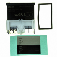
... Totalizer in the event of a long period without use. Be sure to remove this sheet before attempting to use the product. Remove the insulation sheet and press the Reset Key on the front panel of the Counter. (With the H7ER-N,-NV(-H),-NV1(-H), models, “0” or “0.0” will be displayed after 1 s.) Insulation Sheet Reset Key • ...
Page 30
... AC/DC Multi-voltage Input Models • When connecting count/timer input from an SSR to the Counter that operates with AC/DC voltage input, use OMRON’s G3TA-IA/ID SSR (for DC) whose leakage current is 0.1 mA max. or connect a bleeder resistor in parallel to the input circuit of the Counter. ...
Page 31
... Press the Reset Key before use (not necessary for H7ER-N,-NV,- NV1). (5) Tool (1) (1) (3) (4) (5) ■ PCB-mounting Counter Power Supply • Use the power supply within the applicable range indicated by the following waveform, while considering the ripple and voltage fluctu- ations of the circuit power source. ...
Page 32
... V rms max. and 42.4 V peak max VDC max. Cleaning To prevent damage, the exterior of the Counter must not be exposed to organic solvents (3.g. paint thinner or benzine), strong alkalis, or strong acids. Others • No user-serviceable parts. • Return to OMRON for all repairs. H7E@-N@P Large-current- consuming components H7E@-N@P Bypass ...
Page 33
... Please read and understand this catalog before purchasing the products. Please consult your OMRON representative if you have any questions or comments. WARRANTY OMRON's exclusive warranty is that the products are free from defects in materials and workmanship for a period of one year (or other period if specified) from date of sale by OMRON. OMRON MAKES NO WARRANTY OR REPRESENTATION, EXPRESS OR IMPLIED, REGARDING NON-INFRINGEMENT, MERCHANTABILITY, OR FITNESS FOR PARTICULAR PURPOSE OF THE PRODUCTS ...