LC4H-R4-AC240V Panasonic Electric Works, LC4H-R4-AC240V Datasheet - Page 7
LC4H-R4-AC240V
Manufacturer Part Number
LC4H-R4-AC240V
Description
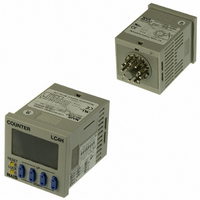
COUNTER DIGITAL 240VAC OCT 11PIN
Manufacturer
Panasonic Electric Works
Series
LC4Hr
Datasheet
1.LC4H-R4-DC24V.pdf
(45 pages)
Specifications of LC4H-R4-AC240V
Count Rate
30Hz or 5kHz Selectable
Number Of Digits/alpha
4
Input Type
Switch Closure or Transistor Switch
Output Type
Switch Closure
Voltage - Supply
100 V ~ 240 V
Display Type
LCD Red/Yellow
Lead Free Status / RoHS Status
Lead free / RoHS Compliant
Other names
255-1218
Available stocks
Company
Part Number
Manufacturer
Quantity
Price
Company:

Part Number:
LC4H-R4-AC240VS
Manufacturer:
Panasonic Electric Works
Quantity:
135


LC4H/-L
Setting the operation mode and set value
Setting procedure 1) Setting the operation mode (input mode and output mode)
Setting procedure 2) Setting the set value
• Changing the set value
1. It is possible to change the set
value with the up and down keys (4-
digit type only) even during counting.
However, be aware of the following
points.
1) If the set value is changed to less than
the count value with counting set to the
addition direction, counting will continue
until it reaches full scale (9999 with the
4-digit type and 999999 with the 6-digit
type), returns to zero, and then reaches
the new set value. If the set value is
changed to a value above the count
value, counting will continue until the
count value reaches the new set value.
120
Set the input and output modes with the DIP switches on the side of the counter.
DIP switches
Set the set value with the UP and DOWN keys on the front of the counter.
Front display section
• 4-digit display type
Q Counter display
W Set value display
E Controlled output indicator
R Reset indicator
T Lock indicator
Y UP keys
• 6-digit display type
Q Counter display
W Set value display
E Controlled output indicator
R Reset indicator
T Lock indicator
1
2
3
4
5
6
7
8
Changes the corresponding
digit of the set value in the
addition direction (upwards).
Minimum reset input signal width
Maximum counter speed
(Same for 6-digit and screw terminal types)
Output mode
Input mode
1
2
Item
3
4
5
6
7
8
DIP switches (See note 2)
2) Suppose that the counter is preset to
count down. Whether a preset count-
down value is smaller or larger than the
count value, the counter counts down to
“0(Zero)”.
2. If the set value is changed to “0,”
the unit will not complete count-up. It
starts counting up when the counting
value comes to “0 (Zero)” again.
1) Up-count (addition) input when count-
ing is set to the addition direction, count-
ing will continue until full scale is reached
(9999 with the 4-digit type and 999999
with the 6-digit type), return to zero, and
then complete count-up.
20 ms
30 Hz
OFF
Refer to table 1
Refer to table 2
4
5
8
9
3
3
5
7
8
4
DIP switch
5 kHz
1 ms
LC4H
ON
RESET
RESET
LOCK
LOCK
O P .
R S T
L O C K
O P .
R S T
L O C K
DOWN
COUNTER
UP
COUNTER
Table 1: Setting the output mode
Table 2: Setting the input mode
Notes:1) The counter and set value displays will display DIP Err.
Notes:2) Set the DIP switches before installing the counter on the panel.
Notes:3) When the DIP SW setting is changed, turn off the power once.
Notes:4) The DIP switches are set as ON before shipping.
LC4H
OFF
OFF
OFF
OFF
OFF
OFF
OFF
OFF
ON
ON
ON
ON
ON
ON
ON
ON
1
6
DIP switch No.
DIP switch No.
OFF
OFF
OFF
OFF
OFF
OFF
OFF
OFF
ON
ON
ON
ON
ON
ON
ON
ON
2
7
1
7
2
6
1
2
6
OFF
OFF
OFF
OFF
OFF
OFF
OFF
OFF
ON
ON
ON
ON
ON
ON
ON
ON
2) Down-count (subtraction) input when
counting is set to the subtraction direc-
tion, counting will continue until full scale
is reached (-999 with the 4-digit type and
-99999 with the 6-digit type), and then
the display will change to
the 4-digit type and
6-digit type. The counting value does not
become “0” and so the counter does not
count up.
3) For directive, independent, and phase
input, when the counting value increases
or decreases from the value "0" and then
returns back to the value "0," count-up is
completed.
3
8
U DOWN keys
I RESET switch
O LOCK switch
Y UP keys
U RESET switch
I LOCK switch
Changes the corresponding digit of
the set value in the subtraction
direction (downwards).
Resets the counting value and the
output.
Locks the operation of all keys on
the counter.
Changes the corresponding digit of
the set value in the addition direc-
tion (upwards).
Resets the counting value and the
output.
Locks the operation of all keys on
the counter.
SHOT-A
SHOT-B
SHOT-C
SHOT-D
HOLD-A
HOLD-B
HOLD-C
—
Addition input
Subtraction input
Directive input
Independent input
Phase input
—
—
—
(See note 1)
(See note 1)
(See note 1)
(See note 1)
Output mode
Input mode
with the
with