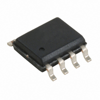
W181-01G Cypress Semiconductor Corp, W181-01G Datasheet - Page 3

W181-01G
Manufacturer Part Number
W181-01G
Description
CLOCK EMI REDUCTION SSCG 8-SOIC
Manufacturer
Cypress Semiconductor Corp
Series
Premis™r
Type
Clock/Frequency Synthesizer, Spread Spectrum Clock Generatorr
Datasheet
1.W181-01G.pdf
(9 pages)
Specifications of W181-01G
Pll
Yes
Input
Clock, Crystal
Output
CMOS
Number Of Circuits
1
Ratio - Input:output
1:1
Differential - Input:output
No/No
Frequency - Max
75MHz
Divider/multiplier
Yes/No
Voltage - Supply
3.135 V ~ 5.5 V
Operating Temperature
0°C ~ 70°C
Mounting Type
Surface Mount
Package / Case
8-SOIC (3.9mm Width)
Frequency-max
75MHz
Lead Free Status / RoHS Status
Contains lead / RoHS non-compliant
Other names
428-1395
Available stocks
Company
Part Number
Manufacturer
Quantity
Price
Company:
Part Number:
W181-01G
Manufacturer:
TEXAS
Quantity:
224
Part Number:
W181-01G
Manufacturer:
CYPRESS/赛普拉斯
Quantity:
20 000
Part Number:
W181-01GI
Manufacturer:
CYPRESS/赛普拉斯
Quantity:
20 000
Part Number:
W181-01GT
Manufacturer:
PTC
Quantity:
20 000
Document #: 38-07152 Rev. *D
Because the modulating frequency is typically 1000 times
slower than the fundamental clock, the spread spectrum
process has little impact on system performance.
Frequency Selection With SSFTG
In Spread Spectrum Frequency Timing Generation, EMI
reduction depends on the shape, modulation percentage, and
frequency of the modulating waveform. While the shape and
frequency of the modulating waveform are fixed for a given
frequency, the modulation percentage may be varied.
Spread Spectrum Frequency Timing
Generation
The device generates a clock that is frequency modulated in
order to increase the bandwidth that it occupies. By increasing
the bandwidth of the fundamental and its harmonics, the ampli-
tudes of the radiated electromagnetic emissions are reduced.
This effect is depicted in Figure 2.
As shown in Figure 2, a harmonic of a modulated clock has a
much lower amplitude than that of an unmodulated signal. The
reduction in amplitude is dependent on the harmonic number
and the frequency deviation or spread. The equation for the
reduction is:
dB = 6.5 + 9*log
where P is the percentage of deviation and F is the frequency
in MHz where the reduction is measured.
Reference Input
Clock Input
10
(P) + 9*log
Divider
Freq.
10
Q
(F)
Feedback
Detector
Divider
Phase
Figure 1. Functional Block Diagram
P
Charge
Pump
GND
V
DD
Using frequency select bits (FS1:2 pins), the frequency range
can be set. Spreading percentage is set to be 1.25% or 3.75%
(see Table 1).
A larger spreading percentage improves EMI reduction.
However, large spread percentages may either exceed
system maximum frequency ratings or lower the average
frequency to a point where performance is affected. For these
reasons, spreading percentages between 0.5% and 2.5% are
most common.
The output clock is modulated with a waveform depicted in
Figure 3. This waveform, as discussed in “Spread Spectrum
Clock Generation for the Reduction of Radiated Emissions” by
Bush, Fessler, and Hardin produces the maximum reduction
in the amplitude of radiated electromagnetic emissions.
Figure 3 details the Cypress spreading pattern. Cypress does
offer options with more spread and greater EMI reduction.
Contact your local Sales representative for details on these
devices.
Modulating
Waveform
Σ
PLL
VCO
Dividers
Post
CLKOUT
(EMI suppressed)
Page 3 of 9
W181


