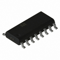
SY10EL34LZC Micrel Inc, SY10EL34LZC Datasheet - Page 3

SY10EL34LZC
Manufacturer Part Number
SY10EL34LZC
Description
IC CLK GEN /2/4/6 5V/3.3V 16SOIC
Manufacturer
Micrel Inc
Series
10EL, Precision Edge®r
Type
Clock Generatorr
Datasheet
1.SY100EL34LZG.pdf
(5 pages)
Specifications of SY10EL34LZC
Pll
No
Input
ECL, PECL
Output
Clock
Number Of Circuits
1
Ratio - Input:output
1:3
Differential - Input:output
Yes/Yes
Divider/multiplier
Yes/No
Voltage - Supply
3 V ~ 3.8 V
Operating Temperature
0°C ~ 85°C
Mounting Type
Surface Mount
Package / Case
16-SOIC (3.9mm Width)
Number Of Outputs
6
Operating Supply Voltage (max)
-3.8V
Operating Temp Range
0C to 85C
Propagation Delay Time
1.2ns
Operating Supply Voltage (min)
-3V
Mounting
Surface Mount
Pin Count
16
Operating Supply Voltage (typ)
-3.3V
Package Type
SOIC
Operating Temperature Classification
Commercial
Lead Free Status / RoHS Status
Contains lead / RoHS non-compliant
Frequency-max
-
Lead Free Status / Rohs Status
Not Compliant
Micrel, Inc.
NOTE:
Z = LOW-to-HIGH transition
ZZ = HIGH-to-LOW transition
V
NOTE:
1. Parametric values specified at:
V
NOTES:
1. Parametric values specified at:
2. Skew is measured between outputs under identical transitions.
3. Minimum input swing for which AC parameters are guaranteed. The device will function reliably with differential inputs down to 100mV.
4. The CMR range is referenced to the most positive side of the differential input signal. Normal operation is obtained if the HIGH level falls within the specified
M9999-031006
hbwhelp@micrel.com or (408) 955-1690
Symbol
I
V
I
Symbol
t
t
t
t
V
V
t
t
EE
EE
EE
IH
PD
skew
S
H
r
f
DC ELECTRICAL CHARACTERISTICS
AC ELECTRICAL CHARACTERISTICS
TRUTH TABLE
BB
PP
CMR
range and the peak-to-peak voltage lies between V
assume a nominal V
CLK
= V
= V
ZZ
Z
X
EE
EE
Power Supply
Current
Output Reference 10EL –1.43
Voltage
Input High Current
Propagation Delay to
Output
Within-Device Skew
Set-up Time EN
Hold Time EN
Minimum Input Swing
Common Mode Range
Output Rise/Fall Times
Q (20% – 80%)
(Min.) to V
(Min.) to V
Parameter
Parameter
EN
H
L
X
EE
= –3.3V. Note for PECL operation, the V
EE
EE
(Max.); V
(Max.); V
100EL
100EL –1.38
10EL
(2)
CLK
MR
(3)
MR
(4)
H
L
L
5 volt Power Supply Range
3 volt Power Supply Range
5 volt Power Supply Range
3 volt Power Supply Range
CC
CC
Min.
Min.
–1.3
—
—
—
960
650
400
200
250
275
= GND
= GND
—
T
T
Divide
Hold Q
Reset Q
A =
A =
Typ.
1100
Typ.
PP
—
—
—
—
—
800
400
—
—
—
—
—
–40 C
–40 C
Function
min. and 1V. The lower end of the CMR range varies 1:1 with V
0–2
0–2
–1.30 –1.38
–1.26 –1.38
Max.
150
Max.
1200
1010
–0.4
49
49
525
50
—
—
—
(1)
(1)
CMR
Min.
Min.
–1.4
—
—
—
960
650
400
200
250
275
100EL34 Series:
10EL34 Series
10/100EL34L Series:
100EL34 Series:
10EL34 Series
10/100EL34L Series:
—
(min) will be fixed at 3.3V – IV
3
T
T
A =
Typ.
A =
1100
Typ.
800
400
—
—
—
—
—
—
—
—
—
—
0 C
0 C
–1.27 –1.35
–1.26 –1.38
Max.
150
Max.
1200
1010
–0.4
49
49
525
50
—
—
—
Min.
-4.2V to -5.5V.
-4.75V to -5.5V.
-3.0V to -3.8V.
-4.2V to -5.5V.
-4.75V to -5.5V.
-3.0V to -3.8V.
Min.
–1.4
—
—
—
960
650
400
200
250
275
—
T
T
A =
CMR
A =
Typ.
1100
Typ.
—
—
—
—
—
800
400
+25 C
—
—
—
—
—
+25 C
(min)I.
–1.25 –1.31
–1.26 –1.38
Max.
150
Max.
1200
1010
–0.4
49
49
525
50
—
—
—
EE
Min.
. The numbers in the spec table
Min.
–1.4
—
—
—
960
650
400
200
250
275
—
T
T
A =
A =
Typ.
1100 1200
Typ. Max.
—
—
—
—
—
800
400
+85 C
—
—
—
—
—
+85 C
Precision Edge
SY100EL34/L
–1.19
–1.26
Max.
1010
–0.4
150
SY10EL34/L
525
49
54
50
—
—
—
Unit
Unit
mA
mV
ps
ps
ps
ps
ps
V
V
A
®


