2-111494-0 TE Connectivity, 2-111494-0 Datasheet

030 UNIV I/O 30DP SLOT LTCH

2-111494-0

Manufacturer Part Number
2-111494-0
Description
030 UNIV I/O 30DP SLOT LTCH
Manufacturer
TE Connectivity
Series
Universal I/Or
Datasheets

Specifications of 2-111494-0

Product Line
AMP-LATCH
Connector Type
Connector Assembly
Shrouded
Yes
Termination Method To Wire/cable
IDC
Ul File Number
E28476
Csa File Number
LR 7189
Mating Post Length (mm [in])
6.10 [0.240]
Panel Mount Retention
With
Panel Mount Retention Type
Mounting Ear(s)
Contact - Rated Current (a)
1
Operating Voltage Reference
AC
Operating Voltage (vac)
250
Wire/cable Size (awg)
26 – 28
Wire/cable Size (mm²)
0.08 – 0.15
Wire/cable Size (cma)
158 – 296
Profile Height (y-axis) (mm [in])
23.75 [0.935]
Number Of Positions
30
Centerline (mm [in])
2.54 [0.100]
Row-to-row Spacing (mm [in])
2.54 [0.100]
Number Of Rows
2
Mating Retention
With
Length (x-axis) (mm [in])
62.89 [2.476]
Width (z-axis) (mm [in])
8.38 [0.3299]
Contact Type
Pin
Contact Base Material
Phosphor Bronze
Contact Plating, Mating Area, Material
Gold Flash over Palladium Nickel or Gold (30) over Nickel
Contact Plating, Mating Area, Thickness (µm [?in])
0.762 [30]
Tail Plating Material
Matte Tin
Connector Style
Plug
Mating Alignment
With
Mating Alignment Type
Keyed
Housing Color
Black
Ul Flammability Rating
UL 94V-0
Rohs/elv Compliance
RoHS compliant, ELV compliant
Lead Free Solder Processes
Not relevant for lead free process
Rohs/elv Compliance History
Always was RoHS compliant
Agency/standard
UL, CSA
Ul Rating
Recognized
Ul Voltage Rating (vac)
250
Operating Temperature (°c [°f])
-65 – +105 [-85 – +221]
Applies To
Wire/Cable
Accepts Wire Insulation Diameter, Range (mm [in])
0.81 – 0.97 [0.032 – 0.0381]
Application Use
Wire-to-Wire
Contact Transmits (typical Application)
Signal (Data)
Packaging Method
Tray
1.
1.1.
1.2.
1.3.
2.
2.1.
3.
3.1.
3.2.
3.3.
3.4.
©2011 Tyco Electronics Corporation,
a TE Connectivity Ltd. Company
All Rights Reserved
TE logo is a trademark.
SCOPE
Content
This specification covers performance, tests and quality requirements for AMP-LATCH* Universal
input/output (I/O) pin connector.
Connector Assembly Definition
I/O pin connector contacts in housings crimped to .050 inch centerline ribbon cable with #28 and 26
solid and stranded AWG conductors. Completed assemblies mate to receptacle connectors.
Qualification
When tests are performed on subject product line, procedures specified in 109-Series Test
Specifications shall be used. All inspections shall be performed using applicable inspection plan and
product drawing.
APPLICABLE DOCUMENTS
The following documents form a part of this specification to the extent specified herein. In the event of
conflict between requirements of this specification and product drawing, product drawing shall take
precedence. In the event of conflict between requirements of this specification and referenced
documents, this specification shall take precedence.
TE Connectivity (TE) Documents
A.
B.
C.
D.
E.
REQUIREMENTS
Design and Construction
Product shall be of design, construction and physical dimensions specified on applicable product
drawing.
Material
A.
B.
Ratings
A.
B.
Performance and Test Description
Product is designed to meet electrical, mechanical and environmental performance requirements
specified in Figure 1. All tests are performed at ambient environmental conditions per Test Specification
109-1 unless otherwise specified.
109-1:
109 Series:
108-40000:
114-7011:
501-219: Test Report
Contact: Phosphor bronze
Housing and cover:
Current: 1 ampere maximum (single circuit energized), see Para 3.5.(c)
Temperature: -65 to 105° C, unless limited by tem perature rating of cable used
General Requirements for Test Specifications
Product
Specification
AMP-LATCH* Universal I/O Pin Connector
| Indicates Change
*Trademark
Test Specifications as indicated in Figure 1.
Product Specification
Application Specification
Black thermoplastic, UL94V-0
Other products, logos, and company names might be trademarks of their respective owners.
For latest revision, visit out website at www.te.com/documents
For Regional Customer service, visit our website at www.te.com
108-1336
11 Mar 11 Rev A
1 of 6
LOC B

Related parts for 2-111494-0

2-111494-0 Summary of contents

Page 1

... This specification covers performance, tests and quality requirements for AMP-LATCH* Universal input/output (I/O) pin connector. 1.2. Connector Assembly Definition I/O pin connector contacts in housings crimped to .050 inch centerline ribbon cable with #28 and 26 solid and stranded AWG conductors. Completed assemblies mate to receptacle connectors. 1.3. Qualification When tests are performed on subject product line, procedures specified in 109-Series Test Specifications shall be used ...

Page 2

... Test Specification 109-28-4. Subject mated connectors to 5.43 G's RMS between 5-500 HZ with 100 ma current applied. See Figure 3. Test Specification 109-21-7, Condition E. Subject mated connectors to 100 G's sawtooth shock pulses of 11 milliseconds duration. 3 shocks in each direction applied along 3 mutually perpendicular planes, 18 total shocks ...

Page 3

... Procedure Subject unmated connectors to 5 cycles between -65 and 105° C. Test Specification 109-22. Subject unmated connectors to 10 humidity-temperature cycles between 25 and 65°C at 95% RH. Test Specification 109-23-4, Condition B. Subject mated connectors to environmental class III for 20 days for 15 and 30 microinch gold plating. Test Specification 109-85- 3 ...

Page 4

... Testing for test group 1 shall be performed on minimum and maximum mounted connector sizes available. Testing for test group 2 shall be performed on maximum free hanging connector size available. Testing for test groups 3 and 4 shall be performed on mid-range mounted connectors ...

Page 5

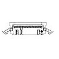
Quality Conformance Inspection The applicable quality inspection plan will specify sampling acceptable quality level to be used. Dimensional and functional requirements shall be in accordance with applicable product drawing and this specification. Rev A Figure 3 Vibration & Physical ...

Page 6

Termination Resistance Measurement Points Rev A Figure 4 108-1336 ...

Related keywords